Fundamental Rules of Probability Computations

2.1.1 Basic axioms of probability

The three basic axioms of probability computation are (1) nonnegativity: P (A) > 0, (2) totality: P (S) = 1, with S being the sample space, and (3) additivity: For two mutually exclusive events A and B, P(A U B) = P(A) + P(B).

As indicated from axioms (1) and (2), the value of probability of an event occurring must lie between 0 and 1. Axiom (3) can be generalized to consider K mutually exclusive events as

P (A1 U A2 U-.-U Ak ) = p( U aA =£) P (Ak) (2.2)

‘vk=1 ‘ k=1

An impossible event is an empty set, and the corresponding probability is zero, that is, P(0) = 0. Therefore, two mutually exclusive events A and B have zero probability of joint occurrence, that is, P (A, B) = P (0) = 0. Although the prob­ability of an impossible event is zero, the reverse may not necessarily be true. For example, the probability of observing a flow rate of exactly 2000 m3/s is zero, yet having a discharge of 2000 m3/s is not an impossible event.

Relaxing the requirement of mutual exclusiveness in axiom (3), the probabil­ity of the union of two events can be evaluated as

P(A U B) = P(A) + P(B) – P(A, B) (2.3)

which can be further generalized as

/ K N K

W ^AkJ = £ P (Ak) – ££P ( a Aj •

^ ‘ k = 1 i < j

+ EEE P(At, A, Ak) -■ ■ ■ + (-1)KP(A1, A2,…, Ak)

i < j < k

(2.4)

If all are mutually exclusive, all but the first summation term on the right-hand side of Eq. (2.3) vanish, and it reduces to Eq. (2.2).

Example 2.1 There are two tributaries in a watershed. From past experience, the probability that water in tributary 1 will overflow during a major storm event is 0.5, whereas the probability that tributary 2 will overflow is 0.4. Furthermore, the probability that both tributaries will overflow is 0.3. What is the probability that at least one tributary will overflow during a major storm event?

Solution Define Ei = event that tributary i overflows for i = 1, 2. From the prob­lem statements, the following probabilities are known: P(E]_) = 0.5, P(E2) = 0.4, and P(E1, E2) = 0.3.

The probability having at least one tributary overflowing is the probability of event E1 or E2 occurring, that is, P(E1 U E2). Since the overflow of one tributary does not preclude the overflow of the other tributary, E1 and E2 are not mutually exclusive. Therefore, the probability that at least one tributary will overflow during a major storm event can be computed, according to Eq. (2.3), as

P(E1 U E2) = P(E1) + P(E2) – P(E1, E2) = 0.5 + 0.4 – 0.3 = 0.6

Removal Methods and Containment

K. A. Trimbler has described and compared methods of lead paint removal. His findings are summarized in Table 1.15 and described below. (K. A. Trimbler, Industrial Lead Paint Removal Handbook, 2d ed., Steel Structures Painting Council/KTA-Tator, Inc., Pittsburgh, 1993, and personal communication, August 2002.)

Quality of preparation Debris created

Rust/mill

Equipment

investment"

Paint removal^

scale removal^

Quality for painting"

Dust

Method and name

Flat

Irregular

Flat

Irregular

generation^

of debris^

required^

rate"

Method 1. Open abrasive blast cleaning with expendable abrasives

2-4 f

5

5

5

5

5

і

і

1-2

5

Method 2. Open abrasive blast cleaning with recyclable abrasives

1

5

5

5

5

5

3

4

1

5

Method 3. Closed abrasive blast cleaning with vacuum

1

5

3-4

5

3-4

5

4-5

4

4

2

Method 4. Wet abrasive blast cleaning

2-3 f

5

5

5

5

4-5

4-5

1

2-3

4

Method 5. High-pressure water jetting

2

3-4

2-3

1

1

3-5

5

2-4

2-4

3

Method 6. High-pressure water jetting with abrasive injection

2

5

4-5

5

4-5

4-5

5

2-3

2-4

3-4

Method 7. Ultrahigh-pressure water jetting

1

4-5

3-4

1

1

3-5

5

2-4

2-4

4

Method 8. Ultrahigh-pressure water jetting with abrasive injection

1

5

4-5

5

4-5

4-5

5

2-3

2-4

4

Method 9. Hand-tool cleaning

5

1-2

1-2

1

1

1-3

4-5

4

4

2

Method 10. Power-tool cleaning Method 11. Power-tool cleaning

4

2-3

2

1-2

1-2

1-3

3-4

4

4

2

with vacuum attachment

3

2-3

2

1-2

1-2

1-3

4-5

4

4-5

2

Method 12. Power-tool cleaning to bare metal

4

4-5

2-3

4-5

2-3

4-5

3

4

3-4

1-2

Method 13. Power-tool cleaning to bare metal with vacuum attachment

3

4-5

2-3

4-5

2-3

4-5

4-5

4

4-5

1-2

Method 14. Chemical stripping

3-4

3-4

3

1

1

2-5

5

2-3

3-4

1

Method 15. Sponge jetting

2-3

5

5

4-5

4-5

5

4

3-4

3-4

2-3

Method 16. Sodium bicarbonate blast cleaning

2-3

3

2-3

1-2

1-2

3-4

4-5

2-4

2-4

2-3

Method 17. Carbon dioxide blast cleaning

1

2-3

2-3

1

1

3-4

4-5

4

4

1-2

Method 18. Combinations of removal methods

Ratings dependent upon combinations of methods used.

Method 19. Abrasive blasting with proprietary additive for lead stabilization^

2-4

5

5

5

5

5

1

1

1-2

4-5

Method 20. Thermal spray vitrification^

1

3-4

2-4

1

1

2-5

4-5

4

3-4

1

Method 21. Laser paint removal^

1

3-4

1-2

1

1

2-5

4-5

5

3-4

1

a5, very inexpensive; 4, inexpensive; 3, moderately expensive; 2, expensive; 1, very expensive.

b5, highly effective; 4, effective; 3, moderately effective; 2, poor; 1, very poor (ineffective).

c5, excellent; 4, good; 3, marginal; 2, poor; 1, very poor.

d5, no/none; 4, little/low; 3, moderate; 2, sizable; 1, substantial.

e5, very high; 4, high; 3, moderate; 2, low; 1, very low.

fMost contractors already own much of this equipment. Therefore, even though the purchase price is high, little additional investment may be needed.

£ Additional methods supplied by K. A. Trimbler, 2002, with ratings for these specific methods developed based on general experience.

Source: From K. A. Trimbler, Industrial Lead Paint Removal Handbook, 2d ed., Steel Structures Painting Counci 1/KTA-Tator, Inc., Pittsburgh, 1993, with permission, and

personal communication, 2002.

Open Abrasive Blast Cleaning with Expendable Abrasives. In this method, compressed air propels blasting grit against the coated surface. The spent blasting grit is then collected for disposal. The major advantages of this method are that contractors are familiar with this long-practiced method, it is very effective in creating a superior surface preparation, it reaches areas otherwise difficult to access, and it is relatively quick (seperate con­tainment considerations). The major disadvantage of this method is that it creates a high level of leaded dust and large quantities of debris that typically must be disposed of as haz­ardous waste. The additional containment requirements, hygiene training, and personal protection equipment requirements increase the cost of removal.

Open Abrasive Blast Cleaning with Recyclable Abrasives. In this method, metallic abra­sives are used to remove the paint. The abrasives can be separated from the debris (paint, rust, mill scale) and reused. The volume of dust and debris is reduced as compared to open abra­sive blast cleaning with expendable abrasives, but the effectiveness and the ability to reach inaccessible areas are the same. Additional disadvantages are contractors’ unfamiliarity with the method and the special care that must be taken to keep the blasting grit moisture-free to avoid rusting and clumping. Should the abrasive dust escape containment, it may cause rust spots on the surfaces where it settles. Because the grit is recycled, higher concentrations of airborne lead dust within the containment area will have to be considered for worker safety.

Closed Abrasive Blast Cleaning with Vacuum. A third method is to apply a compressed-air propellant from a nozzle fitted with a localized containment assembly that employs a vacuum. The recycled metallic grit, dust, and debris are vacuumed as the surface is blasted. This method is rated as highly effective, both in surface preparation and in containment of dust and debris, but the rate of cleaning is slow. The greatest limitation of this method is that the containment mask must be held tightly to the surface of the structure, reducing the method’s effectiveness on irregular and inaccessible surfaces. The containment method confines the blast spray pat­tern so that only small surface areas are being blasted at any one time. This requirement, along with the need to maintain a tight seal, is arduous and leads to operator fatigue.

Wet Abrasive Blast Cleaning. In the wet abrasive method, water is injected into a stream of slag abrasive propelled by compressed air. This method is effective both in dust control and in the quality of surface preparation; however, the amount of waste produced is sub­stantial and difficult to clean up. Inhalation hazard is greatly reduced with this method, but the potential for ingestion still exists.

High-Pressure Water Jetting. High pressure water (20,000 lb/in2 or 138 MPa) propelled against the surface is effective without the use of grit. This method reduces dust to negli­gible levels; however, the potential for ingestion still exists. The water is voluminous and difficult to capture in containment. The method is not effective in removing paint from rel­atively inaccessible areas or in removing mill scale. A rust inhibitor is usually used as part of this method, which may affect the applied coating.

High-Pressure Water Jetting with Abrasive Injection. Combining the previous method with abrasive injection results in all the advantages and disadvantages of the previous methods but with the additional complication of having grit in the disposal water. It is con­sidered highly effective in removing mill scale and paint from inaccessible areas.

Ultrahigh-Pressure Water Jetting. Even more highly pressurized water (up to 40,000 lb/in2 or 276 MPa) can be propelled against the surface without the use of grit. This method is more efficient in removing paint than the high-pressure water jetting method; however, the main advantages and disadvantages of the high-pressure water jetting method still apply.

Ultrahigh-Pressure Water Jetting with Abrasive Injection. The ultrahigh-pressure water jet method can be enhanced by the addition of disposable abrasives to the jet stream. The result is rated highly effective, with advantages and disadvantages similar to those of the previously described water jetting methods.

Hand-Tool Cleaning. Manually operated impact tools and scrapers can be used to remove paint and mill scale. This method is relatively inexpensive, but is relatively ineffec­tive compared to other methods. Since only small amounts of localized dust and debris are created, workers may have a false sense of security about exposure, thus making it difficult to enforce personal protective equipment requirements.

Power-Tool Cleaning. Power tools such as chippers, needle guns, descalers, wire brushes, sanding disks, and grinding wheels can be used to remove paint, rust, and scale from the bridge surface. This is a labor-intensive method. The resulting quality of preparation of the surface may be inadequate, depending on the condition of the coating being removed. Airborne dust is generated, and workers must be properly protected.

Power-Tool Cleaning with Vacuum Attachment. In another version of the previous method, a vacuum attachment is added around power tools and debris. This has the disad­vantage that accessibility in tight areas is reduced because of the shroud and vacuum attach­ment. On irregular surfaces, a seal may be difficult to maintain, and airborne leaded dust may be present. Because a seal typically minimizes dust, workers may not be aware when it has slipped and they thus require additional respiratory protection.

Power-Tool Cleaning to Bare Metal. Power tools can also be used to clean to the bare metal. This method adds such tools as scarifiers (rotary peening tools) to the power-tool set and can achieve a generally higher level of surface preparation. More dust is created, and higher levels of worker protection and training are required. Productivity is low, and a high quality of surface preparation may not be achieved in inaccessible or heavily pitted areas.

Power-Tool Cleaning to Bare Metal with Vacuum Attachment. A modification of the previous method contains dust and debris using a shroud and a vacuum attachment around the scarifying power tools, creating a seal with the bridge surface. This has the same dis­advantages as the method of power-tool cleaning with vacuum attachment, but with addi­tional training required on the equipment and greater cost to achieve bare-metal standards.

Chemical Stripping. Chemical stripping agents can be applied to the surface, left in place for several hours, and then scraped off along with paint, rust, and scale. The surface must then be flushed with water and the chemical agent neutralized. The rinse material must be contained and disposed of properly. This method virtually eliminates airborne debris. Personal protective clothing must be worn during the removal process to prevent dermal contact with leaded debris. However, not all chemicals are effective on all paints, and few will remove all the rust and scale.

Sponge Jetting. In the sponge jetting method, compressed air is used to propel polyurethane particles (sponge) that may be seeded with abrasives against the bridge surface. The debris and sponges are collected and sorted. The sponges can then be reused. The quality of surface preparation is similar to that from other blast cleaning methods, but the productivity is lower. The amount of debris is significantly reduced because of the recycling of the sponges. Visible dust is reduced, although containment and personal protection gear must be maintained as in other blasting methods. Costs of the equipment and abrasives are high.

Sodium Bicarbonate Blast Cleaning. Either jetted water or compressed air can be used to propel water-soluble sodium bicarbonate against the bridge surface. This method does not remove mill scale or rust effectively. Dust is significantly reduced when jetted with water, thereby reducing the potential for lead inhalation, but lead ingestion remains a hazard. Containment of the water is difficult. It may be demonstrated on a case-by-case basis that the sodium bicarbonate serves to stabilize lead in the paint so that it does not leach into the water in concentrations great enough to render the blasting water a hazardous waste. There is no grit waste. This method requires inhibitors to prevent flash rust from forming when the paint is removed.

Carbon Dioxide Blast Cleaning. Small pellets of dry ice can be propelled using com­pressed air against the bridge surface. This method does not remove mill scale or heavy rust, and production is slow. This method reduces the volume of waste to only the actual paint being removed. It also greatly reduces sparking risk, and dust is reduced. Worker exposure is reduced, though it must still be controlled. The equipment and materials for this method are relatively expensive.

Combinations of Removal Methods. Combining methods, if done effectively, may reduce the volume of waste or increase productivity or the quality of surface preparation. The objec­tive is to select methods that are complementary. An example would be first using a chemi­cal stripper, which yields low dust and minimizes the need for containment. The chemicals will remove the leaded paint but not the mill scale. Once the hazardous substances are removed, another method, such as wet blasting, can remove the mill scale and rust without necessitating further hazardous waste disposal.

Abrasive Blasting with Proprietary Additive for Lead Stabilization. The equipment and procedures used are identical to open abrasive blasting, except that the abrasive is pre­blended with a proprietary material that stabilizes the lead, typically creating a nonhazardous waste for disposal.

Thermal Spray Vitrification. This method involves the application of molten glass to the surface that binds with the coating. Upon cooling, the glass/paint composite cracks, and spontaneously disbonds from the surface.

Laser Paint Removal. This method involves the use of lasers to instantaneously vapor­ize the paint, turning it into an ash that is vacuumed for disposal.

Design Constraints

Information you’ve gathered thus far will be use­ful whether you’re hiring a general contractor and an architect or trying to tackle various parts of the job yourself. But before you begin explor­ing design solutions, consider realities that will have an impact on your plans.

BUDGET CONSTRAINTS

Consult a licensed general contractor (GC) about construction costs, especially before asking an architect to generate a lot of design options, called schematic drawings. An experienced con­tractor can cite construction costs per square foot in your region but may be reluctant to do so without qualifying those estimates. Such quali­fiers will be well founded because every renova­tion is different, and there’s no way of knowing what surprises a job holds till you open up walls and floors. Most contractors won’t charge for a brief exploratory meeting, they’re courting a client, after all; but if consultations drag on, be prepared to pay consulting time. Fair’s fair.

In this initial meeting, you’re trying to get ballpark figures so you can see if your plans are realistic. Typically a contractor will offer costs per square foot for “vanilla” space such as bed­rooms or living rooms as well as for more com­plicated spaces such as kitchens and bathrooms. Armed with those preliminary numbers, be pre­pared to modify and trim the scope of your proj­ect so you can stay within your budget when you proceed with detailed designs. Try not to proceed with plans you can’t presently afford, unless you are prepared to complete the work in phases, which could mean living with an unfinished ren­ovation, perhaps for years.

CONSTRAINTS FROM PLANNING DEPARTMENTS

Once you’ve mapped the house, but before you sketch any proposed solutions, visit the planning department in your community to learn the ground rules for remodeling. Additions or other expansions of the physical envelope of your house need to be checked against regulations governing setbacks, lot coverage, height limits, parking requirements, and so on. An addition may also be subject to a design review, and you may need to apply for a variance, depending on the scope of the project. A variance may require that you obtain the approval of neighbors. Thus an early visit to local authorities could prevent your falling too deeply in love with a design you won’t be allowed to build.

STYLISTIC CONSTRAINTS

As you renovate, respect what’s already there. Design is tricky stuff to articulate, but a build­ing’s integrity comes from the proportion of its windows to walls, the width and contour of its trim, the slope of its roof—in short, from its parts, just as we humans are distinctive by the color of our hair, the set of our eyes, and the shape of our nose.

Each historical period has its distinctive architectural elements, and generally you’re bet­ter off not mixing them. When you must change something, be guided by what’s there. If your house has been modified by earlier owners and you question their judgment, walk around the neighborhood with your camera looking for other houses of the same period. Often, nearby houses will have been built from similar plans or even by the same builder. Here, digital photo­graphs are useful because, once you load them into your computer, you can readily modify them with a software program, such as PhotoShop™.

Review of Materials Applied as Fillers

3.2.4.1 Commercially Produced Fillers (Added Fillers)

According to European terminology,! added fillers are made by crushing stone to produce fillers aimed at use in highway engineering. For a long time, the most popu­lar of these has been, and is likely to remain, limestone filler. Limestone filler is distinguished by its affinity with binder, which is one of its strong points. Therefore in Europe limestone filler is most often used for SMA.

The other important feature of industrially manufactured fillers is their repeat­ability and uniformity of parameters. Finally it is worth observing their constant and repeatable mineralogical composition.

3.2.4.2 Fly ashes

The use of fly ashes as fillers for SMA is uncommon. Their disadvantages include large specific area (fly ashes are very fine) and the spherical shape of the grains. So fly ashes have only been used to a limited extent and always need an engineering assessment before use.

The density of fly ashes is lower than that of crushed rocks or baghouse fines and fluctuates between 2.0 and 2.6 g/cm3. To obtain a similar volume share in a mineral
blend, ashes are metered in at a lower weight than a standard filler. The modified Rigden void content is usually less than 50% (Report FHWA-IF-03-019, 2003).

Mortar—F:B Index

One popular approach used during design practice in many countries is to indicate the recommended range of the filler-bitumen ratio (or F:B index) by weight or vol­ume. Researchers in the United States have said that this factor better describes the maximum content of filler in the mix than does setting specific limits on the filler content. It is also worth adding that those studies have defined the maximum F:B index for asphalt concrete at the level of 1.2-1.5 (by weight) (Anderson, 1987). The F:B index was later altered to 0.6-1.6 in the Superpave method (Superpave Mixture Design Guide. WesTrack Forensic Team Consensus Report, 2001). Finally the sug­gested F:B ratio for SMA mixes is at 1.5 by weight, taking the total amount of dust on aggregates and added filler as the filler content (Harris and Stuart, 1995). But the F:B index has been criticized for some time, and there are suggestions regarding its replacement by other factors based on the free binder concept. As an example, Australian research studies (Bryant, 2006) suggest the application of an additional filler fixing factor (FFF) apart from the F:B index. Tests have proved that FFF may be also used to estimate the workability of a mixture.

It is necessary to remember that fillers differ markedly in terms of gradation, den­sity, and void content, therefore formulating a universal F:B index is only an approxi­mation. In fact, such an index should be defined for each filler individually. The goal is clear for each case—to produce a mastic that is neither too dry nor too soft.

Figure 3.4 illustrates the relationship between the content of voids in fillers accord­ing to Rigden’s method and the amount of filler needed to fix binder completely. The higher the F:B index, the more filler is needed to fix the binder. This relationship is illustrated by the graph; the estimated line of completely filled voids in the filler represents the zero-amount of free binder—all the binder is fixed.

As we can see, to fix the binder we need roughly two times more filler that has approximately 30% free voids (the lowest content according to Rigden) than filler that has 50% voids. In the latter case, less filler is sufficient to accommodate all the binder in the free voids (there is a lot of free space for binder within the high void content). It would be difficult for us to use such dependencies unless the filler manufacturer supplies data on the content of free voids according to Rigden or we conduct suitable tests ourselves. All in all, it is better to perform the tests in our own laboratories since eventually a voids parameter may be applied to the entire filler fraction of a mixture (i. e., including the filler fraction that may be coating the coarse and fine aggregate particles).

Another way to evaluate the properties of mortars and the F:B ratio is the applica­tion of the softening point (SP) method. According to a publication from Germany (Schroeder and Kluge, 1992) mortars with SPs between 85°C and 100°C perform

Подпись: 0 і 30 35 40 45 50 Rigden voids, % v/v FIGURE 3.4 Dependence of the F:B index on the content of voids in a dry-compacted filler after Rigden’s method. (Based on van de Ven, M.F.C., Voskuilen, J.L.M., and Tolman, F. The spatial approach of hot mix asphalt. Proceedings of the 6th RILEM Symposium PTEBM’03. Zurich, 2003. With permission.)
well in SMA. Also the Superpave binder test methods could be used for mortar test­ing (DSR[15] and BBR). In Chapter 8, one can find a short description of the methods and some additional remarks.

USING DRILLS

Old drills were made with enclosed trigger guards like those on firearms. Carpenters had their trigger fingers caught and broken from time to time, such as when a drill bit got hung up on a knot in a board and spun suddenly. For safety reasons, workers often used a hacksaw to cut out the trigger guards. These days, manufac­turers have eliminated trigger guards, but that doesn’t mean drills can’t do you harm. To use a drill safely, follow these guidelines:

■ Use clean, sharp bits.

■ Don’t force the drill; let it cut at its own pace.

■ Use a slower speed when drilling harder materials, and coat the bit with wax or silicone to reduce resistance.

■ When drilling thick material, hold the drill with both hands, and use the side handle if the drill comes with one.

■ If you’re drilling a deep hole, pull the bit out of the hole from time to time to clear debris from the bit and the hole.

■ Don’t rely on hand pressure alone to hold the workpiece in which you’re drilling. Instead, clamp the workpiece to a sawhorse or a workbench.

■ Be especially careful when drilling from a ladder. Make sure you have proper balance.

Подпись: New, lightweight tablesaws can be brought to the job site with ease. [Photo by Don Charles Blom] Подпись: carpenters have at least two drills on a job site. A corded drill is best for mixing paint and dry- wall compound and boring holes in concrete, framing lumber, and metal. There are numerous tools out there that can be used to drive screws or drill holes. One of the newer models on the market allows you to drive multiple screws in decking material with no fuss. A cordless impact-driver is another tool that makes driving screws “a walk in the park.” It can set screws with a circular motion or, like a jackhammer, an up-and-down motion that “drives” screws into hard wood or other material. Release the trigger immediately if the bit begins to bind or catch.

USING DRILLS

When you have multiple screws to drive into deck­ing material, try one of these stand-up screw guns.

[Photo by Don Charles Blom]


USING DRILLS

Подпись:Подпись: Many of today's tools are powered by compressed air. Lightweight compressors are easy to move around a job site. [Photo by Don Charles Blom] Подпись: Tool kits, nail bags, and pockets for buckets are available to help keep tools handy and in order. [Photo by Don Charles Blom]

Whether corded or cordless, a drill is usually described by the maximum capacity of its chuck (bit holder). A 3/s-in. model can handle a bit shank diameter of up to 3/s in. For general car­pentry work, buy either a 3/s-in. or a /Tin. drill. Look for a model with a reverse switch (so you can remove screws) and variable speed control.

A good cordless drill will also have a clutch, which makes it easier to drive screws of different sizes. A low clutch setting (1 to 3) is good for driving small screws. Higher settings are used for bigger screws.

Air compressors

For almost sixty years I have been using an air compressor to power the various pneumatic tools used on a job site. The early models took a team of mules to haul around, but many of the compressors we have today can be carried with one arm or have been put on wheels to make maneuvering easier. With the proliferation of air-driven tools, a good air compressor, along with an air hose or two, is a valuable asset. Just make sure workers are given basic safety training and guidelines to avoid injury (see Resources on p. 279).

Accessories for workers

When it comes to tools, work clothes, or tool kits, one size fits all is a thing of the past. These days there are numerous companies (see Resources on p. 279) that offer a good line of work accessories that are tailored for both men and women.

Extension cords

Power tools need adequate power to operate properly, and that means you need good-quality extension cords. The smaller the gauge number marked on the cord, the heavier the wire. The three most common gauges are 12, 14, and 16 (12 is the heaviest). From time to time, I’ve seen carpenters run a circular saw with a 100-ft. 16-gauge extension cord. That’s like watering a lawn with a hose the diameter of a drinking straw. Not much water (or, in the case of an extension cord, electricity) comes through. With

a light extension cord, you risk burning out the motor. To prevent that, always use the shortest cord that will do the job. There’s no need to use a 50-ft. cord if you are working just 15 ft. from an outlet. Here’s a rule you can use for selecting the proper extension cord: Use 16-gauge wire for a 25-ft. (or shorter) cord, 14-gauge wire for a 50-ft. cord, and 12-gauge wire for a 100-ft. cord.

Nominal versus actual size.

Подпись: и їм їм їм и їм їм їм їм їм їм їм їм їм їм їм їм їм їм и їм їм їм їм їм їм їм їм їм їм їм їм їм и їм їм їм їм їм їм їм їм їм їм їм їм їм їм и їм їм їм їм їм їм їм їм їм їм їм їм їм и їм їм їм їм їм їм їм їм і PARTS OF A HOUSE USING DRILLSПодпись: Current issues. Extension cords for builders are designed for outdoor use, with properly sized wires. One good way to store a long cord is to loop it to-gether in a daisy chain.USING DRILLS

Подпись: Proper care of cords is essential. Looping a cord into a daisy chain, or a simple crochet stitch, makes for easy storage (see the photo at left). If a cord is frayed or nicked, repair it. A cord with exposed wires can be extremely dangerous. If that happens, the cord should be cut and rewired with new plugs. You can buy a cord equipped with a built-in ground-fault circuit interrupter (GFCI). In the event of a short, the GFCI automatically shuts off power, preventing electrical shock.

When you shop for lumber, remember the difference between nominal and actual measurements. If you buy a 2×4, you’ll get a IJ/2-in. by 3f2-in. board. If you buy a 2×6, you’ll get a l/^-in. by 5//2-in. board.

Idea of Voids in Dry-Compacted Filler

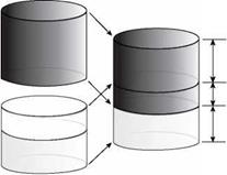
Let us imagine a set of grains that are going to be dry-compacted by tamping.[13] The result will be a mixture with its volume consisting of grains and some free spaces among them. In a regular binder mortar (blend of filler and binder), these free spaces in a compacted filler would be occupied by binder. The rest of binder would remain as excess filler. Thus binder contained in a mortar can be divided into the following two types (Figure 3.2):

Подпись: Volume of binderПодпись:Подпись:Подпись:Подпись:image22"

Idea of Voids in Dry-Compacted Filler

Bulk volume of compacted mineral filler

FIGURE 3.2 Free and fixed binder concept. (From Harris, B. M. and Stuart, K. D., Journal of the Association of Asphalt Paving Technologists, 64, 54-95, 1995; Kandhal, P. S., Journal of the Association of Asphalt Paving Technologists, 50, 150-210, 1981. With permission.)

• Fixed binder—binder inside the voids (filling the voids among compacted filler grains)

• Free binder—excess binder remaining after the voids have been filled

As in the comparison of two fillers with differing gradations, here we may dem­onstrate much the same tendencies—the same quantity of two fillers but with dif­ferent contents of voids may bond differently to the amount of binder. Actually what really matters is the quantity of free binder, because the properties of the mas­tic are dependent on it. The lower the content of free binder in a mortar, the faster the growth of its stiffness (Harris and Stuart, 1995). The minimum amount of free binder has been defined in U. S. research, based on the modified Rigden method, as 30% (v/v) of an asphalt mortar (Anderson, 1987; Chen and Pen, 1998). With that level of free binder, filler grains are suspended in the binder and they do not touch each other. In addition, the rest of the mineral mixture (the coarse aggregate) will be coated by only the free binder, so it is important that a sufficient quantity is available.

Figure 3.3 illustrates the process of gradually filling the voids in a compacted filler; the binder essentially plays two roles—that of a lubricant making the reloca­tion of grains easier and that of a liquid in which they can be suspended.[14]

image24 Подпись: Filter-binder mix with excess binder after voids filled

With a constant content of binder in an asphalt mixture, the quantity of free binder depends on the voids in the compacted filler. With fixed proportions of components in an asphalt mix, the quantity of free binder can be increased by changing to a filler

FIGURE 3.3 Gradually filling the voids in a compacted filler. (From Anderson, D. A., Guidelines on the use of baghouse fines. National Asphalt Pavement Association. Information Series 101-111, 1987b; Harris, B. M. and Stuart, K. D. Journal of the Association of Asphalt Paving Technologists, 64, 54-95, 1995. With permission.)
with a lower void content. Obviously the reverse is also true. The final requirements for the void content in a compacted filler may be defined as follows:

• They cannot be too high—so as to prevent fixing the whole binder, or too much of it, and to leave enough binder for the rest of the asphalt mix— otherwise the mortar will be too dry, stiff, and susceptible to cracking and water damage

• They cannot be too low, because too much unbonded, excess binder will create a greater risk of mix instability, excessive bleeding and binder drain – down, and the deformability (rutting susceptibility) of an asphalt mixture

The following are the recommended contents of voids in a dry-compacted filler:

• When using results of Rigden’s method (test according to EN 1097-4), the mini­mum content of voids in a dry-compacted filler should amount to 28% (v/v) and the maximum content should not exceed 45% (v/v) (Schellenberger, 2002).

• When using results of Rigden’s method modified by Anderson (as in the United States) (test according to Anderson [1987]), the maximum content of voids in a dry-compacted filler should not exceed 50% (v/v) (Brown and Cooley, 1999).

The main factors that influence the content of voids in a dry-compacted filler are as follows (Kandhal, 1981):

• Particle size

• Particle shape

• Particle surface structure

• Particle size distribution

Examples of void contents in various dry-compacted fillers tested according to Rigden’s original method and specific areas according to Blaine’s method [Schellenberger, 2002] are as follows:

4750 cm2/g 3600 cm2/g 2280 cm2/g 2068 cm2/g 2658 cm2/g 4054 cm2/g

Limestone (added filler) 27.7-31.6%

Diabase (baghouse fines) 30.4-34.2%

Limestone (baghouse fines) 28.3-32.1%

Dolomite (added filler) 27.1-28.1%

Dolerite-microdiabase (baghouse fines) 32.4-36.4% Greywacke (baghouse fines) 27.6-31.8%

The following are some sample results of void contents in various dry-compacted fillers according to Rigden’s method modified by Anderson (Schroer, 2006):

Mineral filler 39-47%

Baghouse fines 30-60%

Hydrated lime 66-71%

Fly-ash 37-57%

Generally, the results obtained from Rigden’s original method (as used in Europe) are slightly lower than the results from the modified Rigden method (as used in the United States). The reason is the difference in compactive effort. A similar test, which is an indirect usage of the Rigden voids concept, is the German Filler Test; this test shows good correlation to the modified Rigden method results (see Chapter 8).

MAPPING STRUCTURE AND UTILITIES

Renovations beyond cosmetic changes will prob­ably require some alteration of the structure as well as of plumbing, electrical, and heating/ cooling systems. As with many other aspects of renovation, it’s usually best to disturb as little as possible. Until you demolish walls you won’t know the exact location of every last pipe and wire, but by mapping what you can see, you’ll get a sense of where larger, more problematic ducts and pipes are, and thus save time and money by not proceeding with an obviously impractical design.

Now, using the floor plans you drew earlier as templates, create a map for each house system. For each system, use a tracing-paper overlay or mark up a photocopy of the basic floor plan, whichever is more convenient. While you’re examining each room, it’s also smart to note water stains, tired windows, outdated fixtures, ungrounded outlets, sagging floors, and so on. Use the various house assessment lists in Chapter 1 to guide you.

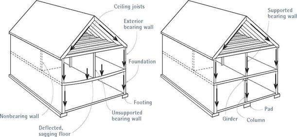
Structural elements should be assessed by a licensed structural engineer, who should also review any design plans that require altering or removing structure. Usually, the big question is whether the walls to be removed are load bear­ing, and that answer is not always obvious. In addition, in high-wind or earthquake regions, walls may be shear walls, which help a building resist lateral (sideways) forces. Don’t cut or drill into, run pipes through, or remove shear walls until a structural engineer has okayed it.

For the best understanding of your house’s structure, start in the basement, where joists and girders are visible, or in an unfinished attic, where rafters and floor joists are frequently exposed. In finished living spaces, wood floors are usually installed perpendicular to joists, so look at flooring-nail patterns. Common sense can be reliable: If the floor slopes down to the base of a wall, there’s a good chance that wall is bearing a load—and may be insufficiently supported.

In most wood-frame houses, bearing walls run perpendicularly to the joists they support, in effect, shortening the distance those joists must span. Bearing walls are usually supported by bearing walls below, on down to the basement, where they will be supported by a girder and posts. However, there are framing eccentricities, especially for additions.

In apartments and row houses, interior walls often aren’t bearing because most apartments are framed with steel girders, and the floors consist

BEFORE AFTER

image65


of reinforced concrete slabs. In row houses, joists and rafters customarily run the width of the house, between exterior walls. Thus interior walls running parallel to joists or rafters are rarely bearing. Partitions running perpendicularly to framing members were probably not bearing walls originally, but they may have become so if joists were undersize to begin with or if their effective spans were reduced by “remuddlers” cutting into them. In such instances partitions may become bearing walls, and floors may slope toward them.

If a wall is nonbearing, removing it may not cause problems. But if it is bearing, you must first transfer the loads it bears to temporary sup­ports, called shoring, before you can alter it. Similarly, avoid removing any structural but­tresses with impunity, such as braces and rafter collar ties. Otherwise unsupported structural elements may sag.

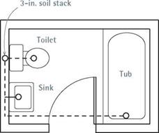
Plumbing fixtures and pipes are usually grouped around a 3-in. or 4-in. soil stack located in a wall near the toilet. Drainpipes are often routed between nearby joists. If the DWV (drainage-waste-vest) system is in decent shape, try not to disturb larger pipes because rerouting them is expensive. Draw fixtures on your plumb­ing map, and note where main drains emerge in the basement and where vent stacks protrude from the roof.

Supply pipes are rarely a design constraint. That is, because supply pipes are smaller and their water is under pressure, they don’t need to
be pitched, as do waste and drainpipes. In many houses, large vents are concealed within “wet walls” framed out with 2x6s that provide plenty of room for even the biggest pipe. Moreover, drains should slope downward at least!4 in. per foot. Thus a 3-in. drain would need almost an 8 in. height for a 12-ft. horizontal run (3h in. for the exterior diameter of pipe, 3 in. for slope, 1 in. of clearance) and, therefore, would need 2×10 joists, as a minimum. Because cutting 4-in. holes through joists would seriously weaken them, it’s

I Plumbing Map______________

image66

Plumbing fixtures are often grouped around a

3- in. or 4-in. soil stack. Because of their size, the soil stack and the main drain it feeds are the most problematic to relocate.

Подпись: I Switch and ReceptacleПодпись: Duplex receptacle (110 volts) 4. Receptacle with ground-fault interrupter 220-volt receptacle S Switch S3 Three-way switch <> Lighting fixture

Use these symbols to map your home’s electrical system. Use different-color felt-tip markers to denote different circuits. See p. 234 for more electrical symbols.

easy to see why large drainpipes almost always need to be routed between joists, rather than through them. If the existing joists don’t provide the height needed to run 3-in. or 4-in. drains, it’s possible to build up a platform over an existing floor or to frame out false ceilings below. Yet if such complications present themselves, consider a simpler design.

Heating and cooling systems can also affect design plans, depending on the type of system. The renovator’s primary concern in placing heat­ing and cooling systems is to make sure that pipes and ductwork do not encounter joists, fire-stops, bridging, or other impediments. Modern hydron – ic (hot-water) heating systems are typically fed by %-in. pipe and so can usually be relocated easily; whereas steam heat, supplied by 112-in. to 2-in. pipe, will require planning. By far, forced hot air (FHA) is the most difficult heating system to plan around because the ducts are so bulky. In this case, where space is tight, false walls, floors, and ceilings are commonly employed. But because the hot air is pushed by a fan, ducts do not need to be sloped upward (although this is desirable) to function well. When renovations require the gutting of wall surfaces, vertical duct runs can easily fit between standard 2×4 studs. Flexible insulated duct greatly expands routing options.

Ventilators for bathrooms and appliances are rarely problematic, since exhaust fans draw air from relatively small, isolated areas. By placing

ovens, cooktops, or stoves near exterior walls or beneath a venting bonnet, you can easily route cooking exhaust to the outside.

When mapping a FHA system, note the loca­tions of registers and the furnace. Then intuit the locations of ductwork, using dotted lines to suggest duct runs. In most cases, ducts or hydronic piping will be visible in the basement. For upper-story heat outlets, delivery ducts and pipes generally travel straight up between studs. In general, avoid running ducts within structural walls, because that would require the cutting of wall plates.

Electrical wiring rarely affects design phases unless you intend to move a service panel. Small and flexible, electrical cable is easily routed through walls, floors, and ceilings. Where you don’t want to cut into existing surfaces, or can’t— as with masonry floors—run rigid conduit or track wiring along the surface.

Mapping the electrical system is best done by two people: one standing at the service panel flip­ping the circuit breakers off and on (or removing fuses from a fused panel), while the other inserts a voltage tester into electrical outlets, as shown in "Using a Voltage Tester,” on p. 235. When the light goes out, you’ve identified the circuit con­trolling it. (Using cell phones to communicate with each other will save a lot of yelling between floors.) It’s difficult to know exactly where cables are, but by noting where cables enter the panel from floors above and using your map of electri­cal circuits, you can make an educated guess.

Finally, map electrical safety as best you can (see Chapter 11). In your survey, did you find ungrounded, two-hole receptacles or grounded, three-hole outlets? Is lighting adequate in bath­rooms and kitchens? Light switches at the top and bottom of stairs? How about shock protec­tion? Kitchen receptacles within 4 ft. of a sink and all bathroom receptacles must be protected by ground-fault circuit interrupters (GFCIs), which cut off power within f4o second when they detect even a slight leak (4 milliamps to 6 milliamps). Local codes may also specify arc-fault circuit interrupters (AFCIs), which can prevent fires caused by loose or corroded electrical connec­tions, nails puncturing wires, and the like. For more about GFCI and AFCI protection, see Chapter 11.

Introduction

L

ight wood-frame construction originated in this country over 150 years ago and quickly evolved into the predominant construction system for houses and other small-scale buildings. Today, over 90% of all new buildings in North America are made using some version of this method. Remodeling projects follow the same track.

There are many reasons why this system has been the choice of professional and amateur builders alike over the years. A principal reason is its flexibility. Because the modules are small, virtually any shape or style of building can be built easily with the studs, joists, and rafters that are the primary components of wood-frame construction. In addition, the pieces are easily handled, the material is readily available, and the skills and tools required for assembly are easily acquired.

Given the popularity of the system, it was surprising to find that, before the publication of the first edition of this book, there existed no detailed and compre­hensive reference focusing on light wood framing.

Now, seventeen years and two editions later, over 275,000 copies of Graphic Guide to Frame Construction have found their way into the libraries of architects, contractors, owner-builders, and students.

The acceptance of the Graphic Guide as a standard reference has corresponded with great strides in building technology. Wood frame buildings today are built faster, stronger, and with more efficient use of materials. Engineered lumber products, relatively rare just 20 years ago, are now more common than sawn lumber for many parts of a building. Wooden buildings are now greatly more resistant to the forces of hurricanes and earthquakes. Vinyl windows, which were just being introduced, are now the standard. Advanced framing that both conserves material and allows for upgraded insulation is rapidly gaining acceptance. These and many other advances were incorporated into the second edition, but the building culture is not static. Best practices are evolving rapidly because of improved communication and building science, and innovative materials are proliferating to meet increased demand.

This third edition expands on those issues covered in the first two editions with the addition of the most recently developed practices and materials.

In particular, this edition updates the details for engineered lumber products and takes a closer look at the important issue of moisture in wood frame building assemblies. These two subjects have dominated the research in recent years and significantly impact each chapter of the book. The topic of environmental responsibility, which has gained serious traction in recent years, has been covered extensively in previous editions but receives further discussion here.

With all the attention given to advanced practices and materials, it is also important not to forget traditional principles and materials. These form the backbone of the system of wood frame construction and are the starting point for the important and considerable work of remodeling and renovation.

Costs and Reports Vary

Whether a basic inspection or an in-depth scientific test, an auditor’s findings will likely be output from software that not only takes into account the physical data about the structure but also data about utility bills, the local climate, and, possibly, comparative information from other houses.

A CMC-trained auditor will generate a report about the existing house’s needed im­provements, including a cost-benefit analy­sis and payback time in years. CMC doesn’t control what its inspectors charge, but Luxton says audits cost from $200 to $400, depending on the size of the house.

RESNET auditors are licensed to use com­pany software that produces a HERS-index report. An audit with a HERS report (report fees can run around $150) costs from $1,000 to $1,500. While BPI doesn’t supply its own software, there are independent programs available that auditors can choose.

An audit from BPI-accredited TerraLogos® in Baltimore costs $495, and though it is thorough in its assessment of and recom­mendations for the house’s existing systems, it does not predict energy savings if the sug­gested upgrades are carried out.

On the other end of the scale is a soup – to-nuts audit done by a company such as Steven Winter Associates. Along with a basic inspection of a house up to 4,000 sq. ft., which includes no scientific testing, the a-la-carte audit menu could include a blower-door test, a duct-leakage test,

Подпись:

Costs and Reports Vary

appliance-combustion testing, infrared – imaging, energy-modeling, and a HERS rat­ing. All this adds up to an audit that costs upward of $2,000.

What’s Next for Energy Audits

The business of energy-auditing is getting huge. "It’s at a tipping point," says Courtney Moriarta, senior engineer at Steven Winter Associates. "Not only do homeowners think it’s a cool thing to do, but it’s also being driven more and more by energy-efficient mortgages and potential tax credits." Both Massachusetts and California are working on legislation that will require house sellers to divulge energy-audit information to pro­spective buyers.

Also on the horizon is a joint energy­auditing standard between RESNET and BPI (which could be adopted by Energy Star, too). Currently in draft form and open to
public comment, the new standard is intended to clear up confusion among homeowners, but the reciprocity between the two organizations will also help audi­tors, many of whom have previously felt the need to get accreditation from both non­profit groups. Steve Baden, executive director of RESNET, says that the standard will recognize the efficacy of all types of energy audits and auditors from "the DIY type to the guy with the clipboard and flash­light to the guy who also uses a blower door and an infrared camera."

Jefferson Kolle is a former editor at Fine Homebuilding.