At-grade intersections should be designed to promote the safe movement of traffic on all legs with a minimal amount of delay to drivers using the intersection. The amount of delay a driver experiences is the measure of effectiveness for signalized intersections as used in capacity analysis. Factors to be considered in designing an intersection are:
• Traffic volumes on all legs, including separate counts for turning vehicles
• Sight distance
• Traffic control devices
• Horizontal alignment
• Vertical alignment
• Radius returns
• Drainage design
• Islands
• Left turn lanes
• Right turn lanes
• Additional through lanes
• Recovery areas
• Pedestrians
• Bicycles
• Lighting
• Development of adjacent property
Traffic Volumes. No intersection can be properly designed without first obtaining accurate traffic counts and reliable projections for the design year of the project. Traffic counts are best determined from actual field counts, including all turning movements, and are broken down by vehicle type. Vehicle types are divided into two groups. The first group includes passenger cars and type A commercial vehicles (pickup trucks and light delivery trucks not using dual tires). The second group includes type B commercial vehicles (tractor, semitrailer, truck-trailer combinations) and type C commercial vehicles (buses, dual-tired trucks with single or tandem rear axles). Adjustments are made to field counts to allow for day of the week, month of the year, time of day, and other site-related factors that may have a significant effect on the counts. Most urbanized areas have regional planning agencies that either provide or certify the traffic data used in intersection design.
Traffic Control. There are four basic types of traffic control at at-grade intersections:
• Cautionary, or nonstop, control
• Stop control for minor traffic
• Four-way stop control
• Signal control
In discussing at-grade intersections, the terms major roadway and minor roadway are sometimes used to distinguish between the two roads. The major roadway usually has a higher functional classification and a greater volume of traffic.
Cautionary, or nonstop, control is used only in special circumstances, such as at an entrance terminal on a freeway. Stop control for the minor roadway is one of the most common treatments found in practice. In these cases, the traffic volumes on the minor roadway are light enough that a signal is not required. The major roadway apparently has volumes low enough to allow gaps for the minor road traffic to enter or cross the intersection. Four-way stop control is effective in situations where the roadways have nearly equal traffic volumes but not great enough volume to justify installing a signal. Finally, signal control is used for intersections where volumes are large enough to preclude using one of the other types.
Sight Distance. Adequate sight distance is an important consideration when designing an at-grade intersection. The alignment and grade on the major roadway should, as a minimum, provide stopping sight distance as given in Table 2.2. The criteria for intersection sight distance (Table 2.3) should also be met wherever possible. Figure 2.7 illustrates the lines of sight involved in intersection design.
Horizontal Alignment Considerations. It is best to avoid locating an intersection on a curve. Since this is often impossible, it is recommended that intersection sites be selected where the curve superelevation is 1/2 in/ft (22 mm/m) or less. It is also recommended that intersections be located where the grade on the major roadway is 6 percent or less, with 3 percent the desirable maximum. Intersection angles of 70° to 90° are provided on new or relocated roadways. An angle of 60° may be satisfactory if right-of-way is to be purchased for a future grade separation and the smaller angle will avoid reconstruction of the intersecting road. In such cases, it may be desirable to locate the intersection so the separation structure can be constructed in the future without disrupting the intersection operation.
Relocation of the minor road is often required to meet the desired intersection location, to avoid roadway segments with undesirable vertical alignments, and to adjust intersection angles. Horizontal curves on the minor roads should be designed to meet the design speed of the road. The minor road alignment should be as straight as possible. Figure 2.31 shows the alignment for a typical rural crossroad relocation.
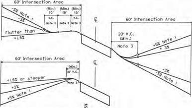
Vertical Alignment Considerations. On roadways with stop control at the intersection, the portion of the intersection located within 60 ft (18 m) of the edge of the mainline pavement is considered to be the intersection area. The pavement surface within this intersection area should be visible to the driver within the limits of the minimum stopping sight distance listed in Table 2.2. By being able to see the pavement surface (height of object of zero), the driver (height of eye of 3.5 ft or 1.07 m) can observe the radius returns and pavement markings and recognize an approaching intersection. Figure 2.32 shows acceptable practice for design of the intersection area.
Combinations of pavement cross slopes and profile grades may produce unacceptable edge of pavement profiles in the intersection area. For this reason, edge of pavement profiles should be plotted and graphically graded to provide a smooth profile. Profile
Note 1. Curve—This portion of the crossroad can occur by itself at “T” type or three-legged intersections.
If possible, the radius of this curve should be commensurate with the design speed of the crossroad. Often, the length of the required profile controls the work length. The horizontal curvature is then chosen so it can be accomplished within this work length. Regardless of the length of the profile adjustment, it is desirable to provide at least a 230-ft (70-m) radius for this curve. When a 230-ft (70-m) radius incurs high costs, it is permissible to reduce this radius to a minimum of 150 ft (46 m).
Note 2. Tangent and Approach Radii—The crossroad in this area should have a tangent alignment. For the condition shown, the alignment between the radius returns is tangent from one side of the road to the other. However, at some intersections with a minor through movement (for example, crossroad intersections of standard diamond ramps) it may be desirable to provide different intersection angles on each side of the through road.
Note 3. Curve—The statements in (1) above also apply to this curve. With the reverse curve condition shown, the radius will often not exceed 250 ft (76 m) because flatter curves make the relocation extraordinarily long.
Note 4. Tangent—This tangent should be approximately 150 ft (46 m) in length for 30 or 40 mi/h (48 or 64 km/h) design speeds on the existing road, and approximately 250 ft (76 m) for 50 or 60 mi/h (80 or 97 km/h) design speeds. These lengths are generous enough to allow reasonable superelevation transitions between the reverse curves. In general, it is usually not desirable to make this tangent any longer than required. If a longer tangent can be used, the curvature or intersection angle can be improved and these two design items are more important.
Note 5. Curve—This curve should be much flatter than the other two curves. It should be capable of being driven at the normal design speed of the existing crossroad.
FIGURE 2.31 Typical rural crossroad relocation. (From Location and Design Manual, Vol. 1, Roadway Design, Ohio Department of Transportation, with permission)
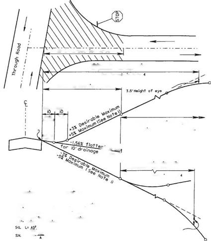 FIGURE 2.32 Crossroad profile for stop condition where through road has normal crown. Conversion: 1 ft = 0.305 m. (From Location and Design Manual, Vol. 1, Roadway Design, Ohio Department of Transportation, with permission)
grades within the intersection area for stop conditions are shown in Figs. 2.32 and 2.33. The grade outside the intersection area is controlled by the design speed of the crossroad. Normal design practices can be used outside the intersection area with the only restriction on the profile being the sight distance required as discussed above.
Grade breaks are permitted at the edge of the mainline pavement for a stop condition. If these grade breaks exceed the limits given in note 3 of Fig. 2.32, they should be treated according to note 3 of Fig. 2.33. Several examples are shown in Fig. 2.33 of the use of grade breaks or short vertical curves adjacent to the edge of through pavement.
Signalized intersections require a more sophisticated crossroad profile. Whenever possible, roadway profiles through the intersection area of a signalized intersection should be designed to meet the design speed of the roads. Grade breaks at signalized
|
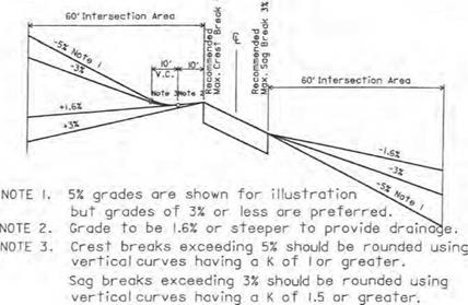
FIGURE 2.33 Crossroad profiles for stop condition where through road is superelevated. Conversion: 1 ft = 0.305 m. (From Location and Design Manual, Vol. 1, Roadway Design, Ohio Department of Transportation, with permission)
|
intersections should be in accordance with Table 2.17. Since the grade break across a normal crowned pavement is usually 3.12 percent, it should be noted that the crown must be flattened. This will allow vehicles on the crossroad to pass through the intersection on a green signal safely without significantly adjusting their speed. The sight distance requirements within the intersection area that were discussed for stop-controlled roadways are also applicable for signalized intersections. Figure 2.34 shows examples of crossroad profiles through a signalized intersection.
Radius Returns at Intersections. Intersection radii in rural areas should normally be 50 ft (15 m), except lesser, but no less than 35 ft (11 m), radii may be used at minor
|
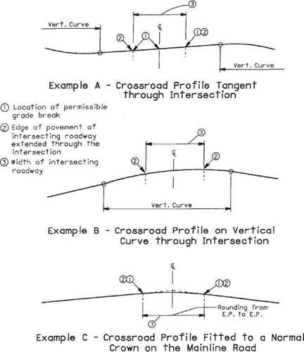
FIGURE 2.34 Examples of crossroad profiles through signalized intersection. (From Location and Design Manual, Vol. 1, Roadway Design, Ohio Department of Transportation, with permission)
|
intersecting roads if judged appropriate for the volume and character of turning vehicles. Radii larger than 50 ft (15 m), a radius with a taper, or a three-center curve should be used at any intersection where the design must routinely accommodate semitrailer truck turning movements. Truck turning templates should be used to determine proper radii and stop bar location. Figure 2.35 shows an example of a turning template for a WB-50 semitrailer truck. Complete sets of turning templates may be obtained from the Institute of Traffic Engineers (Ref. 12). Also available for use with CAD drawings is a CAD-based software product called AutoTURN which is available from Transoft Solutions (Ref. 16). When used in applications with CAD drawings, it reproduces the turning paths for a wide variety of design vehicles. When truck turning
|
12.95 m [42.5 ft] Trailer
|
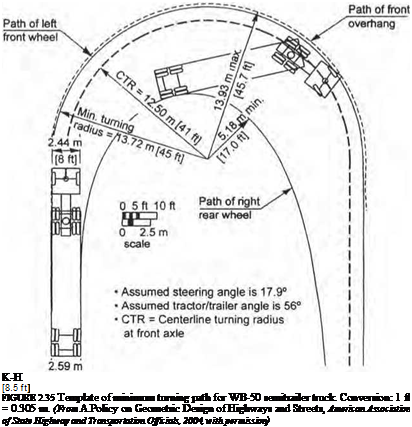
templates are used, a 2-ft (0.6-m) clearance should be provided between the edge of pavement and the closest tire path.
Corner radii at street intersections in urban areas should consider the right-of-way available, the intersection angle, pedestrian traffic, approach width, and number of lanes. The following should be used as a guide:
• Radii of 15 to 25 ft (4.6 to 7.6 m) are adequate for passenger vehicles and may be provided at minor cross streets where there are few trucks or at major intersections where there are parking lanes.
• Radii of 25 ft (7.6 m) or more should be provided at minor intersections on new or reconstruction projects where space permits.
• Radii of 30 ft (9.1 m) or more should be used where feasible at major cross street intersections.
• Radii of 40 ft (12.2 m) or more, three-centered compound curves, or simple curves with tapers to fit truck paths should be provided at intersections used frequently by buses or large trucks.
Drainage Considerations. Within the intersection area, the profile of the crossroad should be sloped wherever possible so the drainage from the crossroad will not flow across the through road pavement. For a stop condition, the 10 ft (3.0 m) of crossroad profile adjacent to the through pavement is normally sloped away from the through pavement, using at least a 1.56 percent grade, as shown in Fig. 2.32. The profiles of curbed radius returns within the intersection may be adjusted to accommodate location of catch basins. It is recommended that exaggerated profiles be used to make adjustments. To ensure smooth transitions around the returns, plot the pavement edges for at least 25 ft (7.6 m) going away from the returns for each leg of the intersection.
Islands at Intersections. In intersection design, an island is defined as an area between traffic lanes that has been delineated to control traffic movements through the intersection. An island may be curbed or uncurbed. It may be concrete, grass, or the same material as the traffic lanes. Islands may be used at intersections for the following reasons:
• Separation of conflicts
• Control of angle of conflict
• Reduction in excessive pavement areas
• Favoring a predominant movement
• Pedestrian protection
• Protection and storage of vehicles
• Location of traffic control devices
Although certain situations require the use of islands, they should be used sparingly and avoided wherever possible. Curbed islands are most often used in urban areas where traffic is moving at relatively low speeds, 40 mi/h (64 km/h) or less, and fixed-source lighting is available. Curbed islands with an area smaller than 50 ft2 (4.6 m2) in urban locations and 75 ft2 (7.0 m2) in rural areas should generally not be used. An area of 100 ft2 (9.3 m2) is preferred in either case. Where pedestrian traffic will be using curbed islands, the islands must be provided with curb ramps. Islands delineated by pavement markings are often preferred in rural or lightly developed areas, when approach speeds are relatively high, where there is little pedestrian traffic, where fixed-source lighting is not provided, or where traffic control devices are not located within the island. Nonpaved islands are normally used in rural areas. They are generally turf and are depressed for drainage purposes.
Left Turn Lanes. Probably the single item having the most influence on intersection operation is the treatment of left-turning vehicles. Left turn lanes are generally desirable at most intersections. However, cost and space requirements do not permit their inclusion in all situations. Intersection capacity analysis procedures should be used to determine the number and use of all lanes. Left turn lanes are generally required under two conditions: (1) when left turn design volumes exceed 20 percent of total directional approach design volumes, and (2) when left turn design volumes exceed 100 vehicles per hour in peak periods.
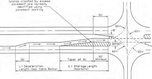
Opposing left turn lanes should be aligned opposite each other because of sight distance limitations. They are developed in several ways depending on the available width between opposing through lanes. Figure 2.36a shows the development required when additional width must be generated. The additional width is normally accomplished by widening on both sides. However, it could be done all on one side or the other. In Fig. 2.36b, the median width is sufficient to permit the development of the left turn lane. Figure 2.37 shows the condition where an offset left turn lane is required to obtain adequate sight distance in wide medians.
In developing turn lanes, several types of tapers may be involved as shown in Fig. 2.36:
Approach taper. An approach taper directs through traffic to the right. Approach taper lengths are calculated using Eq. (2.5) or (2.6).
Departure taper. The departure taper directs through traffic to the left. Its length should not be less than that calculated using the approach taper equations. Normally, however, the departure taper begins opposite the beginning of the full-width turn lane and continues to a point opposite the beginning of the approach taper.
Diverging taper. The diverging taper is the taper used at the beginning of the turn lane. The recommended length of a diverging taper is 50 ft (15 m).
Tables 2.26 and 2.27 have been included to aid in determining the required lengths of left turn lanes at intersections. After determining the length of a left turn lane (Table 2.26), the designer should also check the length of storage available in the adjacent through lane(s) to ensure that access to the turn lane is not blocked by a backup in the through lane(s). To do this, Table 2.27 may be entered using the average number of through vehicles per cycle, and the required length read directly from the table. If two or more lanes are provided for the through movement, the length obtained should be divided by the number of through lanes to determine the required storage length.
It is recommended that left turn lanes be at least 100 ft (30 m) long, and the maximum length be no more than 600 ft (183 m). The width of a left turn lane should desirably be the same as the normal lane widths for the facility. A minimum width of 11 ft (3.4 m) may be used in moderate – and high-speed areas, while 10 ft (3.0 m) may be provided in low-speed areas. Additional width should be provided whenever the lane is adjacent to a curbed median as discussed previously under “Position of Curb.”
Double Left Turn Lanes. Double left turn lanes should be considered at any signalized intersection with left turn demands of 300 vehicles per hour or more. The actual need should be determined by performing a signalized intersection capacity analysis. Fully protected signal phasing is required for double left turns. When the signal phasing permits
|
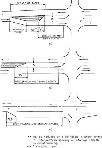
FIGURE 2.36 Turning lane designs showing roadway taper. (a) Left turn lane with no median or median width less than WL. (b) Left turn lane with median wider than WL. (c) Right turn lane. Conversions: 50 ft = 15 m, 100 ft = 30 m. (From Location and Design Manual, Vol. 1, Roadway Design, Ohio Department of Transportation, with permission)
|
simultaneous left turns from opposing approaches, it may be necessary to laterally offset the double left turn lanes on one approach from the left turn lane(s) on the opposing approach to avoid conflicts in turning paths. Figure 2.38 provides an example. All turning paths of double left turn lanes should be checked with truck turning templates allowing 2 ft (0.6 m) between the tire path and edge of each lane. Expanded throat widths are necessary for double left turn lanes as illustrated in Fig. 2.39.

 NOTE
NOTE
I. Determine о minimum length for S by multiplying 8 times The lot era I offset and adding 50 ft.
Using the design Turninq volume, obtain the required storage length from Table 2.26. Use the greater of these^ two numbers for L2. If the length from ТаЫе2.26 is the greater value, increase the tangent area at the intersection.
|
TABLE 2.26 Determination of Length of Left Turn Lanes
|
Type of
traffic control
|
|
Turn demand volume for design speed, mi/h
|
|
30-
|
-35
|
40-
|
-45
|
50-
|
-60
|
|
High
|
Low*
|
High
|
Low*
|
High
|
Low*
|
|
Signalized
|
A
|
A
|
B or C
|
B or C
|
B or C
|
B or C
|
|
Unsignalized stopped crossroad
|
A
|
A
|
A
|
A
|
A
|
A
|
|
Unsignalized through road
|
A
|
A
|
C
|
B
|
B or C
|
B
|
|
|
Conversions: 1 mi/h = 1.609 km/h, 1 ft = 0.305 m.
Condition A: storage only:
Length = 50 ft (diverging taper) + storage length Condition B: high-speed deceleration only:
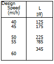
Design speed, mi/h Length (including 50-ft diverging taper), ft
|
40
|
|
125
|
|
45
|
|
175
|
|
50
|
|
225
|
|
55
|
|
285
|
|
60
|
|
345
|
|
Condition C: moderate-speed deceleration and storage:
|
|
Design speed, mi/h
|
Length (including 50-ft diverging taper)
|
|
40
|
111
|
|
|
45
|
125
|
|
|
50
|
143
|
+ storage length
|
|
55
|
164
|
|
|
60
|
181 ,
|
|
*Low is considered 10% or less of approach traffic volume.
^Whichever is greater.
Source: Location and Design Manual, Vol. 1, Roadway Design, Ohio Department of Transportation,
with permission.
|
Right Turn Lanes. Exclusive right turn lanes are less critical in terms of safety than left turn lanes. However, right turn lanes can significantly improve the level of service of signalized intersections. They also provide a means of safe deceleration for rightturning traffic on high-speed facilities and separate right-turning traffic from the rest of the traffic stream at stop-controlled or signalized intersections. As a general guideline, an exclusive right turn lane should be considered when the right turn volume exceeds 300 vehicles per hour per lane.
Figure 2.36c shows the design of right turn lanes. Table 2.27 may be used in preliminary design to estimate the storage required at signalized intersections. The recommended maximum length of right turn lanes at signalized intersections is 800 ft (244 m), with 100 ft (30 m) the minimum length.
The blockage of the right turn lane by the through vehicles should also be checked using Table 2.27. With right-turn-on-red operation, it is imperative that access to the right turn lane be provided to achieve full utilization of the benefits of this type of operation.
The width of right turn lanes should desirably be equal to the normal through lane width for the facility. In low-speed areas, a minimum width of 10 ft (3.0 m) may be provided. Additional lane width should be provided when the right turn lane is adjacent to a curb.
|
TABLE 2.27 Storage Length at Intersections
|
Average no. of vehicles per cycle*
|
Required length, ft
|
Required length, m
|
Average no. of vehicles per cycle*
|
Required length, ft
|
Required length, m
|
|
1
|
50
|
15
|
17
|
600
|
183
|
|
2
|
100
|
30
|
18
|
625
|
190
|
|
3
|
150
|
46
|
19
|
650
|
198
|
|
4
|
175
|
53
|
20
|
675
|
206
|
|
5
|
200
|
61
|
21
|
725
|
221
|
|
6
|
250
|
76
|
22
|
750
|
229
|
|
7
|
275
|
84
|
23
|
775
|
236
|
|
8
|
325
|
99
|
24
|
800
|
244
|
|
9
|
350
|
107
|
25
|
825
|
251
|
|
10
|
375
|
114
|
30
|
975
|
297
|
|
11
|
400
|
122
|
35
|
1125
|
343
|
|
12
|
450
|
137
|
40
|
1250
|
381
|
|
13
|
475
|
145
|
45
|
1400
|
427
|
|
14
|
500
|
152
|
50
|
1550
|
472
|
|
15
|
525
|
160
|
55
|
1700
|
518
|
|
16
|
550
|
168
|
60
|
1850
|
564
|
*Average vehicles/cycle = [DHV (turning lane)]/(cycles/hour)
If cycles/hour are unknown, assume:
Unsignalized or 2-phase—60 cycles per hour
3-phase—40 cycles per hour
4-phase—30 cycles per hour
Source: Location and Design Manual, Vol. 1, Roadway Design, Ohio Department of Transportation,
with permission.
|
Double Right Turn Lanes. Double right turn lanes are rarely used. When they are justified, it is generally at an intersection involving either an off-ramp or a one-way street. Double right turn lanes require a larger intersection radius [usually 75 ft (23 m) or more] and a throat width comparable to a double left turn (Fig. 2.39).
Additional Through Lanes. Normally, the number of through lanes at an intersection is consistent with the number of lanes on the basic facility. Occasionally, through lanes are added on the approach to enhance signal design. As a general suggestion, enough main roadway lanes should be provided that the total through plus turn volume does not exceed 450 vehicles per hour per lane.
Recovery Area at Curbed Intersections. When a through lane becomes a right-turn – only lane at a curbed intersection, an opposite-side tapered recovery area should be considered. The taper should be long enough to allow a trapped vehicle to escape, but not so long as to appear like a merging lane. Taper lengths may vary from 200 to 250 ft (61 to 76 m) depending on design speed.
Pedestrians. Whenever sidewalks approach a curbed intersection, curb ramps must be provided, lining up with the crosswalks. At signalized intersections, when pedestrians are moving concurrently with traffic on one of the phases, sufficient time must be provided on the phase to allow pedestrians to cross the intersection. This is especially significant on intersections with large radii or multiple through lanes. There may be situations where pedestrian volumes will require a separate phase of the signal to be dedicated to their passage.
Islands created by excess pavement are normally Identified using pavement marking


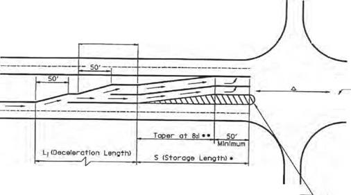
 * Use Table 2.27 to determine storage length. For offset left turn lanes, minimum storage length equals 8 x offset + 50′.
Taper Is used when duolleft turn lanes are offset.
д If opposite approach hos one left turn lane, these lanes should line up.
FIGURE 2.38 Layout for double left turn lanes with lateral offsets. Conversions: 1 mi/h = 1.609 km/h, 1 ft = 0.305 m. {From Location and Design Manual, Vol. 1, Roadway Design, Ohio Department of Transportation, with permission)
A= mostly "P* vehicles, some *SU’ trucks


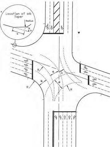
B= sufficient *SU* trucks to govern design, some semitrailers
C= sufficient bus and combination types to govern design
Generally, A is when T < 5X В is when T * 5-Ю»
C is when T > ЮX T= percentage of type В and C trucks in Design AOT
|
F = (W – 24)/2
|
F
|
a
|
b
|
|
<2.0
|
0
|
0
|
|
2.0-3.9
|
40
|
4
|
|
4.0-5.9
|
45
|
6
|
|
6.0-9.0
|
50
|
8
|
|
Other Considerations. On designated bikeway routes, bicycles may have their own lane approaching the intersection. This will require special handling in cases where right-turning vehicles may be crossing the path of through bicycle traffic. The designer should consult with a bicycle facility design reference before proceeding with the intersection design.
Providing fixed-source lighting at intersections, especially in urban areas, is always a safety benefit to drivers. It is particularly important for large-area intersections and channelized intersections, since turning paths may be difficult to determine at night.
The development of adjacent property can sometimes have a detrimental effect on intersection design, since driveways accessing the development may be located too close to the intersection. Whenever possible, accesses to adjacent properties should be located far enough from the intersection so as not to interfere with turn lane design.


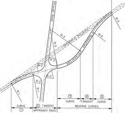
 FIGURE 2.32 Crossroad profile for stop condition where through road has normal crown. Conversion: 1 ft = 0.305 m. (From Location and Design Manual, Vol. 1, Roadway Design, Ohio Department of Transportation, with permission)


 NOTE
NOTE

 * Use Table 2.27 to determine storage length. For offset left turn lanes, minimum storage length equals 8 x offset + 50′.


