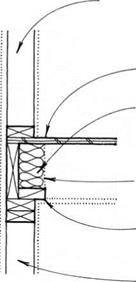
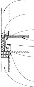
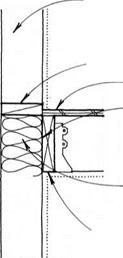
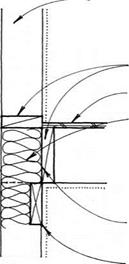
SEALING DOOR BOTTOMS

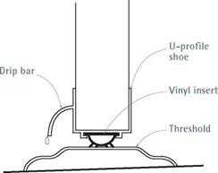
Weatherstripping beneath exterior doors must be weather tight and durable, this because of the heavy traffic it must bear in normal use.

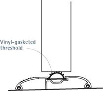
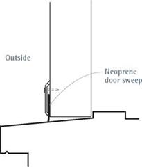
Elements that attach to door bottoms are called shoes or sweeps; those that attach to the floor,
I Weatherstripping Thresholds

image233image234image235

image237

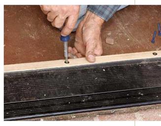
By turning the screws of this adjustable threshold, you can raise and lower the oak strip to get a good seal to the door bottom, thus stopping drafts and water.


image236

Door shoes are usually sized for the ГА-in. thickness of the exterior door. The shoe is cut back about ’/> in. from both sides of the door so the shoe’s drip cap will clear the thicker part of the jamb as the door closes.


Подпись: PROnP Hinges are manufactured so there will be a Ms-in. gap along the hinge jamb when the hinge leaves are mortised flush to the jamb and the door. In other words, when the door is shut, hinge leaves do not quite touch. 1111

thresholds. If the doorway is protected by an overhang, installing a shoe/threshold combination will significantly cut drafts under the door. How­ever, if the doorway is exposed or there are signs of water damage around an existing threshold, cover it with the water-return threshold shown on p. 111. Also see "Floor Pan for Exterior Door,” on p. 97.

Attaching sweeps and shoes is straightforward. The simplest are flap sweeps that are nailed or screwed to the bottom of a door while it’s shut. On an outswinging door, cut the sweep to length and hold it against the bottom edge of the door so the sweep touches the threshold. Flap sweeps are not terribly durable, but they’re cheap and easy to install.

Installing shoes is somewhat more complicated because most types cover the bottom edge of the door and have a vinyl seal. Moreover, you need enough space between the door and the thresh­old to accommodate the thickness of the shoe and its seal (usually Z in., but check manufactur­er’s specs). If not, plane or cut down the door.

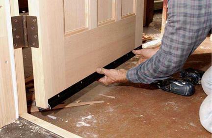
If there is enough space under the door, pull its hinge pins, and lift the door out. Then, using a hacksaw, cut the shoe to length (12 in. shorter at each end than the width of the door). Shoes have screw slots that let you adjust their height; attach the shoe with one screw at each end. Rehang the door, lower the shoe till its seal makes solid con­tact with the existing threshold, tighten the screws at that height, and then open and shut the door. The door should drag slightly as you oper­ate it, and you shouldn’t see daylight under the shut door. When you’re satisfied with the shoe positioning, insert and tighten the rest of the screws in their slots.

Retrofitting a water-return threshold is a bit

more work. A three-piece threshold can be installed over an existing threshold. Consisting of a sill cover, a drain pan, and a threshold with weep holes, the assembly is sloped to send water back outside; hence the name water return.

The retrofit requires accurate measurements and careful cutting so all three pieces fit snugly to the existing door frame. To start, measure the widest point of the doorway opening and rough cut the sill cover to that length; then hold one end of the sill cover square to the base of a jamb and scribe the jamb’s profile onto the metal sill. Use a small circular saw with a metal-cutting blade to cut the first end before scribing and cutting the other end. The sill cover must slope about 18 in. toward the outside so it will shed water. Hold a torpedo level on the sill cover while you tem­porarily shim its back edge up.

Measure and cut the threshold (not the drain pan) next. Usually, the threshold lines up to the outside edge of the doorstop, so when the door shuts, it fits snug to the threshold, as well. As you did with the sill cover, scribe the profile of the jambs onto both ends and cut them out. With the threshold resting on the sill cover, lightly scribe the outside edge of the threshold onto the sill cover, using an awl or a pocketknife. The outer edge of the drain pan should sit just shy of this scribed line. Remove the threshold and scribe the profiles of the jambs onto the drain pan; use avia­tion snips to cut the pan—it’s very thin.

With all three threshold pieces in place (and sloping toward the outside), measure up 12 in. onto each jamb and make pencil marks. The Z in. indicates the thickness of the door shoe you’ll attach to the bottom of the door. Remove the

(continued on p. 112)

Quick Door Fixes[1]

SYMPTOM


CAUSE OR SIGNIFICANCE


WHAT TO DO


Подпись: Loose hinges allowing door to sag into opening Larger-diameter screws won't fit holes in hinges Hinge may be bent Hinges not mortised deep enough into door or frame Hinge leaves set too deep Foundation has settled or framing has shrunk Strike plate is misaligned Подпись: Built-up dirt or floor wax on floor Top track sagging or mechanism needs adjustment Door has fallen off track Подпись: Wheels not turning freely or are rusty; track bent or broken Door off track or stud has bowed into pocket Подпись: Door not fitting tightly to frame Water collecting around doorsill area, soaking wood Absent or poorly installed cap flashing on exterior Metal frames conduct cold; moisture condenses on them Possible foundation settlement

Hinged doors, general

Door binds against top of latch jamb or scrapes floor

Hinge-screw holes in jambs are stripped

Door binds along latch jamb, but hinges are tight

Door binds on latch jamb; hinges are tight; big gap seen along hinge jamb

Door binds along hinge jamb

Door binds because door frame is racked (out of square)

Door shuts but won’t latch

Pocket doors

Door slides roughly

Door slides roughly; floor abraded under door

Door does not slide at all; hard to operate

Door drags, balking at certain points; wheels squeal

Door face abraded; door difficult to operate

Exterior doors

Drafts around door

Water damage to wood doorsill, finish floors, and subfloor

Water stains on interior walls, especially around top of door

Heavy condensation on metal sliding door; floor is water damaged

Door frame not square; casing tilts; large diagonal cracks at corners of doors or windows

Rescrew hinge to jamb, replacing inner screws with ones long enough to reach studs, if needed

Use longer screws or fill holes with white glue, insert toothpicks, allow to dry, and rescrew

Use adjustable wrench to bend hinge-leaf knuckles on door

Remove hinges, chisel hinge gains (recesses) deeper, and reattach hinges

Remove hinges, place cardboard shims under hinges, and reattach

Scribe and trim door to fit skewed opening or replace old frame with squared, prehung door unit

Raise or lower strike plate

Vacuum track thoroughly

Remove trim to expose top-hung mechanism; adjust to raise door

If bottom track, lift door back onto it; if top track, remove trim and set tracking wheels up onto track

Remove trim, swing door out, and oil or replace wheels; use flashlight to examine track inside pocket

Lift door onto track; if problem persists, remove finish wall on one side-may need to replace stud

Install weatherstripping or new threshold

Replaced damaged materials; install water-return threshold to keep water from getting in

Remove siding above top of door frame and retrofit cap flashing

Upgrade to vinyl-clad door with better insulating properties

Have structural engineer check foundation

PRO"ГIP

Metal thresholds are thin enough to cut with hacksaws or jigsaws. But a small (33/s-in.) cordless circular-saw blade is wide enough to track properly and cut square, yet agile enough to notch door-frame profiles. Play it safe: Don’t hand-hold stock while cutting it. Clamp it down so your hands are free. And by all means, wear eye protection and work gloves when cutting metal.

1111

PRO TIP

If hinges are loose because the screw holes are stripped, fill the holes with epoxy putty. Allow that to harden before predrilling and replacing the screws. Don’t bother filling holes with standard wood putty, since it won’t hold.

1111

Stem Wall Reinforcement

Steel bars are placed in footings and stem walls to reinforce the concrete. In situations where the ground is higher than the floor level, such as in a basement or behind a retaining wall, steel reinforcing is also present, often at hor­izontal and vertical intervals of 12 inches or less.

If an owner wishes to eliminate large amounts of conductive metal from struc­tures, it is possible to use fiberglass reinforcing bars. These rebars were originally designed for bridge construction because they do not rust, corrode, or dissolve from galvanic action. Be­cause fiberglass rebar cannot be bent onsite and must be preordered, you should plan well in advance if you wish to use this product. It can be ordered through Tillco or V-rod. If you plan to use fiberglass rebar, ask your local code enforcement officials prior to purchase whether they will accept a particular product. We have used fiberglass rebar successfully in a few homes but have found it to be expensive and inconvenient. You also can reduce electric fields by grounding metal rebar, but the pres­ence of the metal can still provide a potential pathway for stray magnetic fields.

Form Release Agents

Concrete formwork is usually coated with re­lease agents so that it can be easily removed and reused once concrete has cured. Although many inert products may be used for this pur­pose, diesel fuel and other equally noxious substances are commonly used because they are least expensive and readily available. These practices should not be allowed in a healthy house and we suggest the following be speci­fied:

* The use of petroleum-based form oil as a release agent is prohibited. The follow­ing are acceptable for use as form release agents:

• Non-rancid vegetable oil or an accept­able paint specified in Division 9

• Bioform: 100 percent biodegradable form release agent, environmentally safe, VOC compliant, does not freeze

• Crete-Lease: Very low-odor, non-toxic, nonflammable, biodegradable spray-on concrete form release agent

• ELM Concrete Form Release WS: Very low-odor, nontoxic, biodegradable spray-on concrete form release agent

• SOYsolv: Very low-odor, water-based, nontoxic, nonflammable, biodegrad­able spray-on concrete form release agent

Slab Reinforcement

Metal throughout a structure can contribute to electropollution (see Division 16). Placing a mesh of welded wire fabric within a concrete slab to help prevent cracking is common, but this practice can distribute unwanted volt­age throughout the home. Several types of


Подпись: У

the modern applications of a magnesium oxide – based cement. According to a paper by Argonne (anl. gov, search for "Grancrete"), Grancrete is "a tough new ceramic material that is almost twice as strong as concrete [and] may be the key to provid­ing high-quality, low-cost housing throughout de­veloping nations."

The Bindan Company in Chicago (bindancorp. com) makes twelve different products with mag­nesium oxide. Their magnesium oxide/phosphate cements and concretes are some of the strongest ever tested.

A useful application of magnesium oxide is four – by eight-foot panels imported from China and known commercially as Strong-Enviro Board, Dragonboard, and MagBoard. These panels are commonly available in many standard US thick­nesses from Vs to 3Л inch and can fully take the place of plywood, OSB, and drywall in virtually all construction applications. The fiber-reinforced sheets typically meet all UL, ASTM, and ICC re­quirements as replacements for conventional in­terior and exterior sheeting materials. They have a two – to four-hour fire rating, depending on the
thickness, are 100 percent nontoxic, and produce no toxic gases if they burn. More information can be obtained from the manufacturers’ websites, strongenviroboard. com, dragonboard. com, and mag-board. com.

George Swanson holds a Bachelor of Science degree in industrial design from Western Wash­ington University (1975) and is a graduate of the International Institute of Bau-Biologie & Ecology (1992). His firm, Swanson Associates, specializes in the design of healthy and ecological structures us­ing a variety of alternative wail systems. He is cur­rently involved in product development in China and in the importing, distributing, and application of magnesium oxide-based building materials. See geoswan. com.

approved nonmetallic reinforcing fibers are now readily available to do the same job with very little or no increase in cost. Check with local code officials to determine acceptability in your jurisdiction. If wire mesh reinforcing is being excluded, you should add the follow­ing specification:

• Slab reinforcing shall be Уг" fiberglass or

polypropylene fibers as manufactured by

Fibermesh 650 or Novomesh or equal.

Mark exterior walls first

If the deck perimeter isn’t parallel and square, the walls won’t be either. Take the time to check this now, following the procedure explained in Chapter 3 (see pp. 56—57). If necessary, fine-tune the exterior wall layout to correct for out-of-

square corners or nonparallel walls. The lines you snap define the inside edge of the exterior walls. For 2×4 walls, measure 3V2 in. in from the deck edge (slightly more or less if you need to get the walls square and parallel). If the walls will be framed with 2 x6s, use a 51/2-in. measurement. Instead of measuring this dis­tance, you can simply lay a scrap 2x 4 (or 2x 6) on the deck and mark against its inside edge.

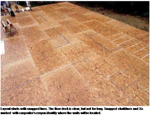
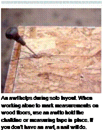
Подпись:Подпись: An awl helps during solo layout. When working alone to mark measurements on wood floors, use an awl to hold the chalkline or measuring tape in place. If you don't have an awl, a nail will do. Подпись: и и in и in и и in и in и и in и и in и in и и in и in и и in и и in и inMark all the exterior corners to establish the layout marks for snapping the exterior wall lines around the perimeter of the floor (or slab).

When you’ve marked all the corners, snap lines around the perimeter. If you’re working on a concrete slab, you may want to move all these lines in an extra У2 in. so that the wall sheathing can be nailed onto the framed wall flush with the concrete. At this point, pay no attention to the openings for doors and windows—just snap the wall lines right through the openings.

Mark interior walls next

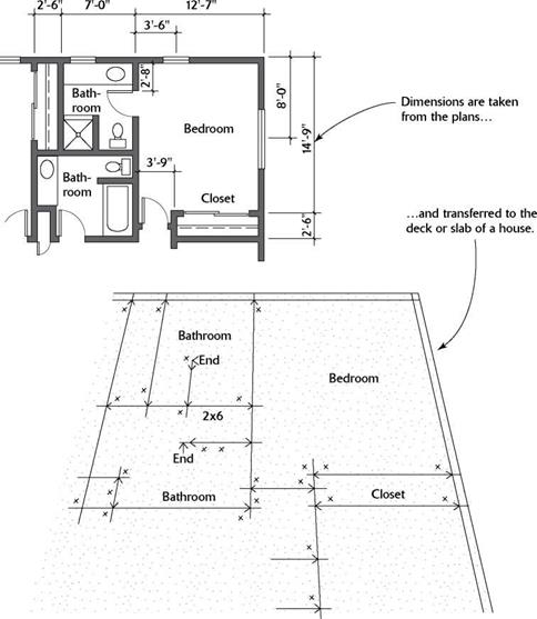
Begin laying out the interior walls by measur­ing from the exterior walls. For example, the illustration on p. 79 calls for a distance of 12 ft. 7 in. from the outside corner of the house to the center of a partition wall. Add or subtract 13/4 in. from that distance to snap the layout line for the partition wall. Remember to note how measurements are given on the plans. Lay out

long interior walls (such as hallways) first, then do the short walls (such as closets). There is no need to mark the door and wall openings.

For hallways, the minimum width is 37 in. in the rough, which yields a finished width of 36 in. (accounting for /Tin. drywall installed on each side). I sometimes frame hallways 40 in. wide in the rough to create easier passage for a wheel­chair (a standard wheelchair is 26 in. wide).

Pay particular attention to squaring bath­rooms and kitchens, which makes it easier to set cabinets and install vinyl flooring. When fram­ing on a slab, plumbing lines will have been set in the concrete. If a pipe was placed slightly outside where a wall should be, it’s better to move the wall rather than the pipe. If the pipe misses the wall by a lot, you’ll need to involve a plumber.

Although a standard bathtub is 60 in. long, I snap wall lines with a 601/8-in. space for the tub, which makes installation easier for the plumber. I also lay out the bathroom’s plumbing wall with a 2×6 wall instead of a 2×4; a wider wall makes it much easier to fit all the bathroom pipes inside.

STEP 1 LAY OUT THE WALLS

I’ve done plenty of house layouts on my own, but it’s better to tackle this job with a helper or two. The work goes faster when you have someone else to hold the other end of the tape or chalkline. More important, your chances of catching mistakes improve significantly.

Read the building plan

A building plan is a guide, just like a road map. There are symbols and measurements to tell you what to do (see the illustration on the facing page). You don’t have to visualize every detail on a road map to get from Texas to Maine. Neither do you have to visualize every detail on a plan to be able to build a house. You just have to know how to read the plan, then take it one step at a time.

The most common plan scale uses 1/4 in. to equal 1 ft., so 1 in. on a plan equals 4 ft. on a subfloor. Plan dimensions, however, can be
labeled as outside to outside, inside to inside, outside to center, or center to center (wall to wall), so you need to pay close attention to this information (see the illustration below). For layout purposes, if you encounter an outside to center (o/s to c) dimension, simply add 13/4 in.—half the width of a 2×4—to the over­all measurement to obtain the outside to outside measurement, which you can then transfer to the floor (for a 2×6 wall, add 23/4 in.).

The first layout work involves transferring key information from the building plans to the subfloor or slab. These layout lines enable you to lay down the top and bottom plates for every wall in the house—a process called plating the walls. With each wall’s top and bottom plates temporarily tacked together on the subfloor, you can mark up the plates to identify exactly where each stud, king stud, header, and trimmer is located. If you haven’t already done so, take the time to familiarize yourself with the various parts that go into a wood-frame wall (see the illustration on p. 87).

Mark wall layouts

Three marking tools are essential: a chalkline, a keel, and a carpenter’s pencil. A chalkline and an ample supply of chalk allow you to snap wall layout lines on the subfloor or slab (see the top photo on p. 80). It’s not necessary to mark two lines for a wall; instead, use a carpenter’s crayon, or keel, to mark an “X” on the side of the line that will be covered by the wall plates. A keel is also useful for labeling parts, writing cripple sizes on headers, and indicating door and win­dow openings.

To make a snapped line easier to find, use a pencil or keel to make a crow’s foot, or a large “V” mark, with the point centered on the line. If you snap a line in error, wipe it away with your foot or at least draw a wavy line through it before snapping a line in the correct place.

Use another chalk color to snap the correct line. Try to keep all markings clear and simple, and avoid complicating things unnecessarily. The object is to get all the information you

STEP 1 LAY OUT THE WALLSSelect the right chalk.

The powdered chalk used for chalklines comes in different colors. Have a second color on hand, in case you need to snap a new chalkline close to an incorrectly snapped line. If you need to lay out walls in wet weather, use water­proof chalk to make sure your lines stay sharp and precise.

Chalklines are snapped on the floor to show the location of all the walls. The top and bottom plates will be tacked to the deck along those lines.

Подпись: Slab plates are important. If you're framing walls on a concrete slab, remember that the bottom plate must be made from pressure-treated lumber. A PT bottom plate will repel termites and resist rot when moisture wicks up from the slab.

need off the plan and onto the floor in an understandable format.

Roadbed Soil Resilient Modulus

The resilient modulus is a measure of the ability of a soil or granular base to resist permanent deformation under repeated loading. Many soils are stress-dependent. As the stress level increases, these soils will behave in a nonlinear fashion. Fine-grain soils tend to be stress-softening, whereas granular soils tend to be stress-hardening. Laboratory procedures for determining resilient modulus have been published by AASHTO as test method T307, or NCHRP as test method 1-38A. A typical setup for the laboratory test is shown in Fig. 3.9. The stress due to the repeated load applied through the load actuator is the deviator stress and is intended to duplicate the effect of loads passing over a section of pavement. The confining stress within the chamber is intended to duplicate the confinement of the soil within the subgrade. A typical load-response curve is shown in Fig. 3.10. As shown, the resilient modulus (MR) is the ratio of deviator stress to strain in the elastic range.

The laboratory procedures for determining resilient modulus are complex and time­consuming. Many equations have been developed relating the resilient modulus to soil properties that are more easily determined. One such property is the California

TABLE 3.11 Axle Load Equivalency Factors for Rigid Pavements, Tandem Axles, and pt of 2.0

Axle load

Slab thickness D, in

kips

kN

6

7

8

9

10

11

12

13

14

2

9

0.0001

0.0001

0.0001

0.0001

0.0001

0.0001

0.0001

0.0001

0.0001

4

18

0.0006

0.0005

0.0005

0.0005

0.0005

0.0005

0.0005

0.0005

0.0005

6

27

0.002

0.002

0.002

0.002

0.002

0.002

0.002

0.002

0.002

8

36

0.006

0.006

0.005

0.005

0.005

0.005

0.005

0.005

0.005

10

44

0.014

0.013

0.013

0.012

0.012

0.012

0.012

0.012

0.012

12

53

0.028

0.026

0.026

0.025

0.025

0.025

0.025

0.025

0.025

14

62

0.051

0.049

0.048

0.047

0.047

0.047

0.047

0.047

0.047

16

71

0.087

0.084

0.082

0.081

0.081

0.080

0.080

0.080

0.080

18

80

0.141

0.136

0.133

0.132

0.131

0.131

0.131

0.131

0.131

20

89

0.216

0.210

0.206

0.204

0.203

0.203

0.203

0.203

0.203

22

98

0.319

0.313

0.307

0.305

0.304

0.303

0.303

0.303

0.303

24

107

0.454

0.449

0.444

0.441

0.440

0.439

0.439

0.439

0.439

26

116

0.629

0.626

0.622

0.620

0.618

0.618

0.618

0.618

0.618

28

125

0.852

0.851

0.850

0.850

0.850

0.849

0.849

0.849

0.849

30

133

1.13

1.13

1.14

1.14

1.14

1.14

1.14

1.14

1.14

32

142

1.48

1.48

1.49

1.50

1.51

1.51

1.51

1.51

1.51

34

151

1.90

1.90

1.93

1.95

1.96

1.97

1.97

1.97

1.97

36

160

2.42

2.41

2.45

2.49

2.51

2.52

2.53

2.53

2.53

38

169

3.04

3.02

3.07

3.13

3.17

3.19

3.20

3.20

3.21

40

178

3.79

3.74

3.80

3.89

3.95

3.98

4.00

4.01

4.01

42

187

4.67

4.59

4.66

4.78

4.87

4.93

4.95

4.97

4.97

44

196

5.72

5.59

5.67

5.82

5.95

6.03

6.07

6.09

6.10

46

205

6.94

6.76

6.83

7.02

7.20

7.31

7.37

7.41

7.43

48

214

8.36

8.12

8.17

8.40

8.63

8.79

8.88

8.93

8.96

50

222

10.00

9.69

9.72

9.98

10.27

10.49

10.62

10.69

10.73

52

231

11.9

11.5

11.5

11.8

12.1

12.4

12.6

12.7

12.8

54

240

14.0

13.5

13.5

13.8

14.2

14.6

14.9

15.0

15.1

56

249

16.5

15.9

15.8

16.1

16.6

17.1

17.4

17.6

17.7

58

258

19.3

18.5

18.4

18.7

19.3

19.8

20.3

20.5

20.7

60

267

22.4

21.5

21.3

21.6

22.3

22.9

23.5

23.8

24.0

62

276

25.9

24.9

24.6

24.9

25.6

26.4

27.0

27.5

27.7

64

285

29.9

28.6

28.2

28.5

29.3

30.2

31.0

31.6

31.9

66

294

34.3

32.8

32.3

32.6

33.4

34.4

35.4

36.1

36.5

68

302

39.2

37.5

36.8

37.1

37.9

39.1

40.2

41.1

41.6

70

311

44.6

42.7

41.9

42.1

42.9

44.2

45.5

46.6

47.3

72

320

50.6

48.4

47.5

47.6

48.5

49.9

51.4

52.6

53.5

74

329

57.3

54.7

53.6

53.6

54.6

56.1

57.7

59.2

60.3

76

338

64.6

61.7

60.4

60.3

61.2

62.8

64.7

66.4

67.7

78

347

72.5

69.3

67.8

67.7

68.6

70.2

72.3

74.3

75.8

80

356

81.3

77.6

75.9

75.7

76.6

78.3

80.6

82.8

84.7

82

365

90.9

86.7

84.7

84.4

85.3

87.1

89.6

92.1

94.2

84

374

101.

97.

94.

94.

95.

97.

99.

102.

105.

86

383

113.

107.

105.

104.

105.

107.

110.

113.

116.

88

391

125.

119.

116.

116.

116.

118.

121.

125.

128.

90

400

138.

132.

129.

128.

129.

131.

134.

137.

141.

Conversion: 1 in = 25.4 mm.

Axle load

Slab thickness D, in

kips

kN

6

7

8

9

10

11

12

13

14

2

9

0.0001

0.0001

0.0001

0.0001

0.0001

0.0001

0.0001

0.0001

0.0001

4

18

0.0003

0.0003

0.0003

0.0003

0.0003

0.0003

0.0003

0.0003

0.0003

6

27

0.0010

0.0009

0.0009

0.0009

0.0009

0.0009

0.0009

0.0009

0.0009

8

36

0.002

0.002

0.002

0.002

0.002

0.002

0.002

0.002

0.002

10

44

0.005

0.005

0.005

0.005

0.005

0.005

0.005

0.005

0.005

12

53

0.010

0.010

0.009

0.009

0.009

0.009

0.009

0.009

0.009

14

62

0.018

0.017

0.017

0.016

0.016

0.016

0.016

0.016

0.016

16

71

0.030

0.029

0.028

0.027

0.027

0.027

0.027

0.027

0.027

18

80

0.047

0.045

0.044

0.044

0.043

0.043

0.043

0.043

0.043

20

89

0.072

0.069

0.067

0.066

0.066

0.066

0.066

0.066

0.066

22

98

0.105

0.101

0.099

0.098

0.097

0.097

0.097

0.097

0.097

24

107

0.149

0.144

0.141

0.139

0.139

0.138

0.138

0.138

0.138

26

116

0.205

0.199

0.195

0.194

0.193

0.192

0.192

0.192

0.192

28

125

0.276

0.270

0.265

0.263

0.262

0.262

0.262

0.262

0.261

30

133

0.364

0.359

0.354

0.351

0.350

0.349

0.349

0.349

0.349

32

142

0.472

0.468

0.463

0.460

0.459

0.458

0.458

0.458

0.458

34

151

0.603

0.600

0.596

0.594

0.593

0.592

0.592

0.592

0.592

36

160

0.759

0.758

0.757

0.756

0.755

0.755

0.755

0.755

0.755

38

169

0.946

0.947

0.949

0.950

0.951

0.951

0.951

0.951

0.951

40

178

1.17

1.17

1.18

1.18

1.18

1.18

1.18

1.18

1.19

42

187

1.42

1.43

1.44

1.45

1.46

1.46

1.46

1.46

1.46

44

196

1.73

1.73

1.75

1.77

1.78

1.78

1.79

1.79

1.79

46

205

2.08

2.07

2.10

2.13

2.15

2.16

2.16

2.16

2.17

48

214

2.48

2.47

2.51

2.55

2.58

2.59

2.60

2.60

2.61

50

222

2.95

2.92

2.97

3.03

3.07

3.09

3.10

3.11

3.11

52

231

3.48

3.44

3.50

3.58

3.63

3.66

3.68

3.69

3.69

54

240

4.09

4.03

4.09

4.20

4.27

4.31

4.33

4.35

4.35

56

249

4.78

4.69

4.76

4.89

4.99

5.05

5.08

5.09

5.10

58

258

5.57

5.44

5.51

5.66

5.79

5.87

5.91

5.94

5.95

60

267

6.45

6.29

6.35

6.53

6.69

6.79

6.85

6.88

6.90

62

276

7.43

7.23

7.28

7.49

7.69

7.82

7.90

7.94

7.97

64

285

8.54

8.28

8.32

8.55

8.80

8.97

9.07

9.13

9.16

66

294

9.76

9.46

9.48

9.73

10.02

10.24

10.37

10.44

10.48

68

302

11.1

10.8

10.8

11.0

11.4

11.6

11.8

11.9

12.0

70

311

12.6

12.2

12.2

12.5

12.8

13.2

13.4

13.5

13.6

72

320

14.3

13.8

13.7

14.0

14.5

14.9

15.1

15.3

15.4

74

329

16.1

15.5

15.4

15.7

16.2

16.7

17.0

17.2

17.3

76

338

18.2

17.5

17.3

17.6

18.2

18.7

19.1

19.3

19.5

78

347

20.4

19.6

19.4

19.7

20.3

20.9

21.4

21.7

21.8

80

356

22.8

21.9

21.6

21.9

22.6

23.3

23.8

24.2

24.4

82

365

25.4

24.4

24.1

24.4

25.0

25.8

26.5

26.9

27.2

84

374

28.3

27.1

26.7

27.0

27.7

28.6

29.4

29.9

30.2

86

383

31.4

30.1

29.6

29.9

30.7

31.6

32.5

33.1

33.5

88

391

34.8

33.3

32.8

33.0

33.8

34.8

35.8

36.6

37.1

90

400

38.5

36.8

36.2

36.4

37.2

38.3

39.4

40.3

40.9

Conversion: 1 in = 25.4 mm.

TABLE 3.13 Axle Load Equivalency Factors for Rigid Pavements, Single Axles, and pt of 2.5

Axle load

Slab thickness D, in

kips

kN

6

7

8

9

10

11

12

13

14

2

9

0.0002

0.0002

0.0002

0.0002

0.0002

0.0002

0.0002

0.0002

0.0002

4

18

0.003

0.002

0.002

0.002

0.002

0.002

0.002

0.002

0.002

6

27

0.012

0.011

0.010

0.010

0.010

0.010

0.010

0.010

0.010

8

36

0.039

0.035

0.033

0.032

0.032

0.032

0.032

0.032

0.032

10

44

0.097

0.089

0.084

0.082

0.081

0.080

0.080

0.080

0.080

12

53

0.203

0.189

0.181

0.176

0.175

0.174

0.174

0.173

0.173

14

62

0.376

0.360

0.347

0.341

0.338

0.337

0.336

0.336

0.336

16

71

0.634

0.623

0.610

0.604

0.601

0.599

0.599

0.599

0.598

18

80

1.00

1.00

1.00

1.00

1.00

1.00

1.00

1.00

1.00

20

89

1.51

1.52

1.55

1.57

1.58

1.58

1.59

1.59

1.59

22

98

2.21

2.20

2.28

2.34

2.38

2.40

2.41

2.41

2.41

24

107

3.16

3.10

3.22

3.36

3.45

3.50

3.53

3.54

3.55

26

116

4.41

4.26

4.42

4.67

4.85

4.95

5.01

5.04

5.05

28

125

6.05

5.76

5.92

6.29

6.61

6.81

6.92

6.98

7.01

30

133

8.16

7.67

7.79

8.28

8.79

9.14

9.35

9.46

9.52

32

142

10.8

10.1

10.1

10.7

11.4

12.0

12.3

12.6

12.7

34

151

14.1

13.0

12.9

13.6

14.6

15.4

16.0

16.4

16.5

36

160

18.2

16.7

16.4

17.1

18.3

19.5

20.4

21.0

21.3

38

169

23.1

21.1

20.6

21.3

22.7

24.3

25.6

26.4

27.0

40

178

29.1

26.5

25.7

26.3

27.9

29.9

31.6

32.9

33.7

42

187

36.2

32.9

31.7

32.2

34.0

36.3

38.7

40.4

41.6

44

196

44.6

40.4

38.8

39.2

41.0

43.8

46.7

49.1

50.8

46

205

54.5

49.3

47.1

47.3

49.2

52.3

55.9

59.0

61.4

48

214

66.1

59.7

56.9

56.8

58.7

62.1

66.3

70.3

73.4

50

222

79.4

71.7

68.2

67.8

69.6

73.3

78.1

83.0

87.1

Conversion: 1 in = 25.4 mm.

Source: Guide for Design of Pavement Structures, American Association of State Highway and

Transportation Officials, Washington, D. C., 1993, with permission.

Bearing Ratio (CBR). Common equations using CBR to calculate resilient modulus values include the following:

E (lb/in2) = 1500 CBR (Shell Oil Co.)

E (lb/in2) = 5409 CBR0 711 (U. S. Army Waterway Experiment Station)

E (lb/in2) = 2550 CBR0 64 (Transport and Road Research Laboratory, England)

(See “Pavement Deflection Analysis,” FHWA Report HI-94-021, NHI, February 1994.) More detailed equations have been developed by correlating laboratory results with fundamental soil properties. R. F. Carmichael III and E. Stuart (“Predicting Resilient Modulus: A Study to Determine the Mechanical Properties of Subgrade Soils,” Transportation Research Record 1043, Transportation Research Board, National Research Council, Washington, D. C., 1985) developed the following models for the U. S. Forest Service:

Axle load

Slab thickness D, in

kips

kN

6

7

8

9

10

11

12

13

14

2

9

0.0001

0.0001

0.0001

0.0001

0.0001

0.0001

0.0001

0.0001

0.0001

4

18

0.0006

0.0006

0.0005

0.0005

0.0005

0.0005

0.0005

0.0005

0.0005

6

27

0.002

0.002

0.002

0.002

0.002

0.002

0.002

0.002

0.002

8

36

0.007

0.006

0.006

0.005

0.005

0.005

0.005

0.005

0.005

10

44

0.015

0.014

0.013

0.013

0.012

0.012

0.012

0.012

0.012

12

53

0.031

0.028

0.026

0.026

0.025

0.025

0.025

0.025

0.025

14

62

0.057

0.052

0.049

0.048

0.047

0.047

0.047

0.047

0.047

16

71

0.097

0.089

0.084

0.082

0.081

0.081

0.080

0.080

0.080

18

80

0.155

0.143

0.136

0.133

0.132

0.131

0.131

0.131

0.131

20

89

0.234

0.220

0.211

0.206

0.204

0.203

0.203

0.203

0.203

22

98

0.340

0.325

0.313

0.308

0.305

0.304

0.303

0.303

0.303

24

107

0.475

0.462

0.450

0.444

0.441

0.440

0.439

0.439

0.439

26

116

0.644

0.637

0.627

0.622

0.620

0.619

0.618

0.618

0.618

28

125

0.855

0.854

0.852

0.850

0.850

0.850

0.849

0.849

0.849

30

133

1.11

1.12

1.13

1.14

1.14

1.14

1.14

1.14

1.14

32

142

1.43

1.44

1.47

1.49

1.50

1.51

1.51

1.51

1.51

34

151

1.82

1.82

1.87

1.92

1.95

1.96

1.97

1.97

1.97

36

160

2.29

2.27

2.35

2.43

2.48

2.51

2.52

2.52

2.53

38

169

2.85

2.80

2.91

3.03

3.12

3.16

3.18

3.20

3.20

40

178

3.52

3.42

3.55

3.74

3.87

3.94

3.98

4.00

4.01

42

187

4.32

4.16

4.30

4.55

4.74

4.86

4.91

4.95

4.96

44

196

5.26

5.01

5.16

5.48

5.75

5.92

6.01

6.06

6.09

46

205

6.36

6.01

6.14

6.53

6.90

7.14

7.28

7.36

7.40

48

214

7.64

7.16

7.27

7.73

8.21

8.55

8.75

8.86

8.92

50

222

9.11

8.50

8.55

9.07

9.68

10.14

10.42

10.58

10.66

52

231

10.8

10.0

10.0

10.6

11.3

11.9

12.3

12.5

12.7

54

240

12.8

11.8

11.7

12.3

13.2

13.9

14.5

14.8

14.9

56

249

15.0

13.8

13.6

14.2

15.2

16.2

16.8

17.3

17.5

58

258

17.5

16.0

15.7

16.3

17.5

18.6

19.5

20.1

20.4

60

267

20.3

18.5

18.1

18.7

20.0

21.4

22.5

23.2

23.6

62

276

23.5

21.4

20.8

21.4

22.8

24.4

25.7

26.7

27.3

64

285

27.0

24.6

23.8

24.4

25.8

27.7

29.3

30.5

31.3

66

294

31.0

28.1

27.1

27.6

29.2

31.3

33.2

34.7

35.7

68

302

35.4

32.1

30.9

31.3

32.9

35.2

37.5

39.3

40.5

70

311

40.3

36.5

35.0

35.3

37.0

39.5

42.1

44.3

45.9

72

320

45.7

41.4

39.6

39.8

41.5

44.2

47.2

49.8

51.7

74

329

51.7

46.7

44.6

44.7

46.4

49.3

52.7

55.7

58.0

76

338

58.3

52.6

50.2

50.1

51.8

54.9

58.6

62.1

64.8

78

347

65.5

59.1

56.3

56.1

57.7

60.9

65.0

69.0

72.3

80

356

73.4

66.2

62.9

62.5

64.2

67.5

71.9

76.4

80.2

82

365

82.0

73.9

70.2

69.6

71.2

74.7

79.4

84.4

88.8

84

374

91.4

82.4

78.1

77.3

78.9

82.4

87.4

93.0

98.1

86

383

102.

92.

87.

86.

87.

91.

96.

102.

108.

88

391

113.

102.

96.

95.

96.

100.

105.

112.

119.

90

400

125.

112.

106.

105.

106.

110.

115.

123.

130.

Conversion: 1 in = 25.4 mm.

TABLE 3.15 Axle Load Equivalency Factors for Rigid Pavements, Triple Axles, and pt of 2.5

Axle load

Slab thickness D, in

kips

kN

6

7

8

9

10

11

12

13

14

2

9

0.0001

0.0001

0.0001

0.0001

0.0001

0.0001

0.0001

0.0001

0.0001

4

18

0.0003

0.0003

0.0003

0.0003

0.0003

0.0003

0.0003

0.0003

0.0003

6

27

0.001

0.001

0.001

0.001

0.001

0.001

0.001

0.001

0.001

8

36

0.003

0.002

0.002

0.002

0.002

0.002

0.002

0.002

0.002

10

44

0.006

0.005

0.005

0.005

0.005

0.005

0.005

0.005

0.005

12

53

0.011

0.010

0.010

0.009

0.009

0.009

0.009

0.009

0.009

14

62

0.020

0.018

0.017

0.017

0.016

0.016

0.016

0.016

0.016

16

71

0.033

0.030

0.029

0.028

0.027

0.027

0.027

0.027

0.027

18

80

0.053

0.048

0.045

0.044

0.044

0.043

0.043

0.043

0.043

20

89

0.080

0.073

0.069

0.067

0.066

0.066

0.066

0.066

0.066

22

98

0.116

0.107

0.101

0.099

0.098

0.097

0.097

0.097

0.097

24

107

0.163

0.151

0.144

0.141

0.139

0.139

0.138

0.138

0.138

26

116

0.222

0.209

0.200

0.195

0.194

0.193

0.192

0.192

0.192

28

125

0.295

0.281

0.271

0.265

0.263

0.262

0.262

0.262

0.262

30

133

0.384

0.371

0.359

0.354

0.351

0.350

0.349

0.349

0.349

32

142

0.490

0.480

0.468

0.463

0.460

0.459

0.458

0.458

0.458

34

151

0.616

0.609

0.601

0.596

0.594

0.593

0.592

0.592

0.592

36

160

0.765

0.762

0.759

0.757

0.756

0.755

0.755

0.755

0.755

38

169

0.939

0.941

0.946

0.948

0.950

0.951

0.951

0.951

0.951

40

178

1.14

1.15

1.16

1.17

1.18

1.18

1.18

1.18

1.18

42

187

1.38

1.38

1.41

1.44

1.45

1.46

1.46

1.46

1.46

44

196

1.65

1.65

1.70

1.74

1.77

1.78

1.78

1.78

1.79

46

205

1.97

1.96

2.03

2.09

2.13

2.15

2.16

2.16

2.16

48

214

2.34

2.31

2.40

2.49

2.55

2.58

2.59

2.60

2.60

50

222

2.76

2.71

2.81

2.94

3.02

3.07

3.09

3.10

3.11

52

231

3.24

3.15

3.27

3.44

3.56

3.62

3.66

3.68

3.68

54

240

3.79

3.66

3.79

4.00

4.16

4.26

4.30

4.33

4.34

56

249

4.41

4.23

4.37

4.63

4.84

4.97

5.03

5.07

5.09

58

258

5.12

4.87

5.00

5.32

5.59

5.79

5.85

5.90

5.93

60

267

5.91

5.59

5.71

6.08

6.42

6.64

6.77

6.84

6.87

62

276

6.80

6.39

6.50

6.91

7.33

7.62

7.79

7.88

7.93

64

285

7.79

7.29

7.37

7.82

8.33

8.70

8.92

9.04

9.11

66

294

8.90

8.28

8.33

8.83

9.42

9.88

10.17

10.33

10.42

68

302

10.1

9.4

9.4

9.9

10.6

11.2

11.5

11.7

11.9

70

311

11.5

10.6

10.6

11.1

11.9

12.6

13.0

13.3

13.5

72

320

13.0

12.0

11.8

12.4

13.3

14.1

14.7

15.0

15.2

74

329

14.6

13.5

13.2

13.8

14.8

15.8

16.5

16.9

17.1

76

338

16.5

15.1

14.8

15.4

16.5

17.6

18.4

18.9

19.2

78

347

18.5

16.9

16.5

17.1

18.2

19.5

20.5

21.1

21.5

80

356

20.6

18.8

18.3

18.9

20.2

21.6

22.7

23.5

24.0

82

365

23.0

21.0

20.3

20.9

22.2

23.8

25.2

26.1

26.7

84

374

25.6

23.3

22.5

23.1

24.5

26.2

27.8

28.9

29.6

86

383

28.4

25.8

24.9

25.4

26.9

28.8

30.5

31.9

32.8

88

391

31.5

28.6

27.5

27.9

29.4

31.5

33.5

35.1

36.1

90

400

34.8

31.5

30.3

30.7

32.2

34.4

36.7

38.5

39.8

Conversion: 1 in = 25.4 mm.

Подпись:
Cohesive soils:

MR = 37.431 – 0.4566(PI) – 0.6179(%W) – 0.1424(S200) +

Подпись: (3.5)0.1791(CS) – 0.3248(DS) + 36.422(CH) + 17.097(MH)

Подпись: where MR PI %W S200 CS DS CH MH resilient modulus, kips/in2 plasticity index percentage water

percentage passing the no. 200 sieve confining stress, lb/in2 deviator stress, lb/in2

1 for CH soil (Unified Soil Classification, Art. 8.3.2)

0 otherwise

1 for MH soil (Unified Soil Classification)

0 otherwise

TABLE 3.17 Axle Load Equivalency Factors for Rigid Pavements, Tandem Axles, andpt of 3.0

Axle load

Slab thickness D, in

kips

kN

6

7

8

9

10

11

12

13

14

2

9

0.0001

0.0001

0.0001

0.0001

0.0001

0.0001

0.0001

0.0001

0.0001

4

18

0.0007

0.0006

0.0005

0.0005

0.0005

0.0005

0.0005

0.0005

0.0005

6

27

0.003

0.002

0.002

0.002

0.002

0.002

0.002

0.002

0.002

8

36

0.008

0.006

0.006

0.006

0.005

0.005

0.005

0.005

0.005

10

44

0.018

0.015

0.013

0.013

0.013

0.012

0.012

0.012

0.012

12

53

0.036

0.030

0.027

0.026

0.026

0.025

0.025

0.025

0.025

14

62

0.066

0.056

0.050

0.048

0.047

0.047

0.047

0.047

0.047

16

71

0.111

0.095

0.087

0.083

0.081

0.081

0.081

0.080

0.080

18

80

0.174

0.153

0.140

0.135

0.132

0.131

0.131

0.131

0.131

20

89

0.260

0.234

0.217

0.209

0.205

0.204

0.203

0.203

0.203

22

98

0.368

0.341

0.321

0.311

0.307

0.305

0.304

0.303

0.303

24

107

0.502

0.479

0.458

0.447

0.443

0.440

0.440

0.439

0.439

26

116

0.664

0.651

0.634

0.625

0.621

0.619

0.618

0.618

0.618

28

125

0.859

0.857

0.853

0.851

0.850

0.850

0.850

0.849

0.849

30

133

1.09

1.10

1.12

1.13

1.14

1.14

1.14

1.14

1.14

32

142

1.38

1.38

1.44

1.47

1.49

1.50

1.51

1.51

1.51

34

151

1.72

1.71

1.80

1.88

1.93

1.95

1.96

1.97

1.97

36

160

2.13

2.10

2.23

2.36

2.45

2.49

2.51

2.52

2.52

38

169

2.62

2.54

2.71

2.92

3.06

3.13

3.17

3.19

3.20

40

178

3.21

3.05

3.26

3.55

3.76

3.89

3.95

3.98

4.00

42

187

3.90

3.65

3.87

4.26

4.58

4.77

4.87

4.92

4.95

44

196

4.72

4.35

4.57

5.06

5.50

5.78

5.94

6.02

6.06

46

205

5.68

5.16

5.36

5.95

6.54

6.94

7.17

7.29

7.36

48

214

6.80

6.10

6.25

6.93

7.69

8.24

8.57

8.76

8.86

50

222

8.09

7.17

7.26

8.03

8.96

9.70

10.17

10.43

10.58

52

231

9.57

8.41

8.40

9.24

10.36

11.32

11.96

12.33

12.54

54

240

1.13

9.8

9.7

10.6

11.9

13.1

14.0

14.5

14.8

56

249

13.2

11.4

11.2

12.1

13.6

15.1

16.2

16.9

17.3

58

258

15.4

13.2

12.8

13.7

15.4

17.2

18.6

19.5

20.1

60

267

17.9

15.3

14.7

15.6

17.4

19.5

21.3

22.5

23.2

62

276

20.6

17.6

16.8

17.6

19.6

22.0

24.1

25.7

26.6

64

285

23.7

20.2

19.1

19.9

22.0

24.7

27.3

29.2

30.4

66

294

27.2

23.1

21.7

22.4

24.6

27.6

30.6

33.0

34.6

68

302

31.1

26.3

24.6

25.2

27.4

30.8

34.3

37.1

39.2

70

311

35.4

29.8

27.8

28.2

30.6

34.2

38.2

41.6

44.1

72

320

40.1

33.8

31.3

31.6

34.0

37.9

42.3

46.4

49.4

74

329

45.3

38.1

35.2

35.4

37.7

41.8

46.8

51.5

55.2

76

338

51.1

42.9

39.5

39.5

41.8

46.1

51.5

56.9

61.3

78

347

57.4

48.2

44.3

44.0

46.3

50.7

56.6

62.7

67.9

80

356

64.3

53.9

49.4

48.9

51.1

55.8

62.1

68.9

74.9

82

365

71.8

60.2

55.1

54.3

56.5

61.2

67.9

75.5

82.4

84

374

80.0

67.0

61.2

60.2

62.2

67.0

74.2

82.4

90.3

86

383

89.0

74.5

67.9

66.5

68.5

73.4

80.8

89.8

98.7

88

391

98.7

82.5

75.2

73.5

75.3

80.2

88.0

97.7

107.5

90

400

109.

91.

83.

81.

83.

88.

96.

106.

117

Conversion: 1 in = 25.4 mm.

Axle load

Slab thickness D, in

kips

kN

6

7

8

9

10

11

12

13

14

2

9

0.0001

0.0001

0.0001

0.0001

0.0001

0.0001

0.0001

0.0001

0.0001

4

18

0.0004

0.0003

0.0003

0.0003

0.0003

0.0003

0.0003

0.0003

0.0003

6

27

0.001

0.001

0.001

0.001

0.001

0.001

0.001

0.001

0.001

8

36

0.003

0.003

0.002

0.002

0.002

0.002

0.002

0.002

0.002

10

44

0.007

0.006

0.005

0.005

0.005

0.005

0.005

0.005

0.005

12

53

0.013

0.011

0.010

0.009

0.009

0.009

0.009

0.009

0.009

14

62

0.023

0.020

0.018

0.017

0.017

0.016

0.016

0.016

0.016

16

71

0.039

0.033

0.030

0.028

0.028

0.027

0.027

0.027

0.027

18

80

0.061

0.052

0.047

0.045

0.044

0.044

0.043

0.043

0.043

20

89

0.091

0.078

0.071

0.068

0.067

0.066

0.066

0.066

0.066

22

98

0.132

0.114

0.104

0.100

0.098

0.097

0.097

0.097

0.097

24

107

0.183

0.161

0.148

0.143

0.140

0.139

0.139

0.138

0.138

26

116

0.246

0.221

0.205

0.198

0.195

0.193

0.193

0.192

0.192

28

125

0.322

0.296

0.277

0.268

0.265

0.263

0.262

0.262

0.262

30

133

0.411

0.387

0.367

0.357

0.353

0.351

0.350

0.349

0.349

32

142

0.515

0.495

0.476

0.466

0.462

0.460

0.459

0.458

0.458

34

151

0.634

0.622

0.607

0.599

0.595

0.594

0.593

0.592

0.592

36

160

0.772

0.768

0.762

0.758

0.756

0.756

0.755

0.755

0.755

38

169

0.930

0.934

0.942

0.947

0.949

0.950

0.951

0.951

0.951

40

178

1.11

1.12

1.15

1.17

1.18

1.18

1.18

1.18

1.18

42

187

1.32

1.33

1.38

1.42

1.44

1.45

1.46

1.46

1.46

44

196

1.56

1.56

1.64

1.71

1.75

1.77

1.78

1.78

1.78

46

205

1.84

1.83

1.94

2.04

2.10

2.14

2.15

2.16

2.16

48

214

2.16

2.12

2.26

2.41

2.51

2.56

2.58

2.59

2.60

50

222

2.53

2.45

2.61

2.82

2.96

3.03

3.07

3.09

3.10

52

231

2.95

2.82

3.01

3.27

3.47

3.58

3.63

3.66

3.68

54

240

3.43

3.23

3.43

3.77

4.03

4.18

4.27

4.31

4.33

56

249

3.98

3.70

3.90

4.31

4.65

4.86

4.98

5.04

5.07

58

258

4.59

4.22

4.42

4.90

5.34

5.62

5.78

5.86

5.90

60

267

5.28

4.80

4.99

5.54

6.08

6.45

6.66

6.78

6.84

62

276

6.06

5.45

5.61

6.23

6.89

7.36

7.64

7.80

7.88

64

285

6.92

6.18

6.29

6.98

7.76

8.36

8.72

8.93

9.04

66

294

7.89

6.98

7.05

7.78

8.70

9.44

9.91

10.18

10.33

68

302

8.96

7.88

7.87

8.66

9.71

10.61

11.20

11.55

11.75

70

311

10.2

8.9

8.8

9.6

10.8

11.9

12.6

13.1

13.3

72

320

11.5

10.0

9.8

10.6

12.0

13.2

14.1

14.7

15.0

74

329

12.9

11.2

10.9

11.7

13.2

14.7

15.8

16.5

16.9

76

338

14.5

12.5

12.1

12.9

14.5

16.2

17.5

18.4

18.9

78

347

16.2

13.9

13.4

14.2

15.9

17.8

19.4

20.5

21.1

80

356

18.2

15.5

14.8

15.6

17.4

19.6

21.4

22.7

23.5

82

365

20.2

17.2

16.4

17.2

19.1

21.4

23.5

25.1

26.1

84

374

22.5

19.1

18.1

18.8

20.8

23.4

25.8

27.6

28.8

86

383

25.0

21.2

19.9

20.6

22.6

25.5

28.2

30.4

31.8

88

391

27.6

23.4

21.9

22.5

24.6

27.7

30.7

33.2

35.0

90

400

30.5

25.8

24.1

24.6

26.8

30.0

33.4

36.3

38.3

Conversion: 1 in = 25.4 mm.

Analysis period


years


Location


Assumed SN or D =____________ in


Roadbed Soil Resilient Modulus

Granular soils:


Roadbed Soil Resilient Modulus

(3.6)


Analysis period =_____ 20____ years

Assumed SN or D =_____ 9_____ in

Current

Growth

Design

ESAL

Design

Vehicle types

traffic (A)

factors (B)

traffic (C)

factor (D)

ESAL (E)

2%

Passenger cars

5,925

24.30

52,551,787

0.0008

42,041

Buses

35

24.30

310,433

0.6806

211,280

Panel and pickup trucks

1,135

24.30

10,066,882

0.0122

122,816

Other 2-axle/4-tire trucks

3

24.30

26,609

0.0052

138

2-axle/6-tire trucks

372

24.30

3,299,454

0.1890

623,597

3 or more axle trucks All single-unit trucks

34

24.30

301,563

0.1303

39,294

3-axle tractor semitrailers

19

24.30

168,521

0.8646

145,703

4-axle tractor semitrailers

49

24.30

434,606

0.6560

285,101

5+ axle tractor semitrailers All tractor semitrailers

1,880

24.30

16,674,660

2.3719

39,550,626

5-axle double trailers

103

24.30

913,559

2.3187

2,118,268

6+ axle double trailers All double trailer combos

0

24.30

3-axle truck-trailers

208

24.30

1,844,856

0.0152

28,042

4-axle truck-trailers

305

24.30

2,705,198

0.0152

41,119

5+ axle truck-trailers All truck-trailer combos

125

24.30

1,108,688

0.5317

589,489

All vehicles

10,193

90,406,816

Design

ESAL

43,772,314

Location

Example 1

Source: Guide for Design of Pavement Structures, American Association of State Highway and

Transportation Officials, Washington, D. C., 1993, with permission.

TABLE 3.21 Equivalency Factors for Determining ESAL

Rigid pavement

Flexible pavement

Function classification

B

C

B

C

Rural interstate

2.27

0.914

1.60

0.735

All other rural

2.16

1.02

1.44

0.777

Urban interstate, freeway, and expressway

2.50

1.48

1.74

1.13

All other urban

1.61

0.673

1.11

0.534

Notes: B = tractor-trucks with semitrailers and trucks with trailers. C = single-unit trucks (2 axles, 6 tires or more).

Source: Ohio Department of Transportation, Location and Design Manual, Vol. 1,

Roadway Design, December 1990, revised October 1992, with permission.

Подпись: LOAD CELL
Подпись: CHAMBER PISTON ROD
Подпись: BALL SEAT (DIVOT)
Roadbed Soil Resilient Modulus
Подпись: LVDT
Подпись: CELL PRESSURE INLET
Подпись: COVER PLATE
Подпись: CHAMBER (lexan or acrylic)
Roadbed Soil Resilient Modulus Подпись: SPECIMEN Roadbed Soil Resilient Modulus

Roadbed Soil Resilient ModulusREPEATED LOAD ACTUATOR

:SOLID BASES

SECTION VIEW

Подпись: NOT TO SCALENote: LVDT tips shall rest on the triaxial cell itself or on a
plate/bracket which is rigidly attached to the tnaxial cell

FIGURE 3.9 Triaxial test chamber for determining resilient modulus of soil specimen. (From NRC Operational Guide No. SHRP-LTPP-OG-004, “SHRP-LTPP Interim Guide for Laboratory Material Handling and Testing," with permission)

FITTINGS

As you are drawing your riser diagrams, you should keep in mind the fittings that will be used for changes in direction. There are three ways to change di­rection. Your pipe can go from horizontal to vertical, from vertical to hori­zontal, or from horizontal to horizontal. The fittings used in a drainage sys­tem to make these changes are regulated by the rules of the local plumbing code. As a rule-of-thumb, you can refer to Figure 4.25 for the common use and acceptance of fittings when changing directions. Again, always confirm local code requirements before committing to a job.

Type

of

fitting

Horizontal

to

vertical

Vertical

to

horizontal

Horizontal

to

horizontal

Sixteenth bend

yes

yes

yes

Eighth bend

yes

yes

yes

Sixth bend

yes

yes

yes

Quarter bend

yes

no

no

Short sweep

yes

yes

no

Long sweep

yes

yes

yes

Sanitary tee

yes

no

no

Wye

yes

yes

yes

Combination wye

yes

yes

yes

and eighth bend

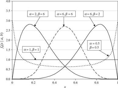
Distributions related to normal random variables

The normal distribution has been playing an important role in the development of statistical theories. This subsection briefly describes two distributions related to the functions of normal random variables.

Distributions related to normal random variables

Distributions related to normal random variables

Figure 2.23 Shapes of standard beta probability density functions. (After Johnson and Kotz, 1972.)


X2 (chi-square) distribution. The sum of the squares of K independent standard normal random variables results in a x2 (chi-square) random variable with K degrees of freedom, denoted as x2- In other words,

E z2 ~ xK (2-101)

k=і

in which the Zks are independent standard normal random variables. The PDF of a x 2 random variable with K degrees of freedom is

f x2(* I K) = 2k/2r1 K/2)x(K/2-1)e-x/2 for x > 0 (2.102)

Comparing Eq. (2.102) with Eq. (2.72), one realizes that the x2 distribution is a special case of the two-parameter gamma distribution with a = K/2 and в = 2. The mean, variance, and skewness coefficient of a xK random variable, respectively, are

ix = K aI = 2 K Yx = 2/v/K72

Thus, as the value of K increases, the x2 distribution approaches a symmetric distribution. Figure 2.24 shows a few x2 distributions with various degrees of freedom. If X1, X2,…, XK are independent normal random variables with the common mean ix and variance a2, the x2 distribution is related to the sample of normal random variables as follows:

1. The sum of K squared standardized normal variables Zk = (Xk – X)/ax, k = 1, 2,…, K, has a x2 distribution with (K – 1) degrees of freedom.

2. The quantity (K – 1)S2/a* has a x2 distribution with (K – 1) degrees of freedom in which S2 is the unbiased sample variance computed according to Table 2.1.

Distributions related to normal random variables

Figure 2.24 Shapes of chi-square probability density functions where d. f. refers to the degrees of freedom.

f-distribution. A random variable having a t-distribution results from the ratio of the standard normal random variable to the square root of the x2 random variable divided by its degrees of freedom, that is,

Z

Tk = (2.103)

Xk / K

in which Tk is a t – distributed random variable with K degrees of freedom. The PDF of Tk can be expressed as

Г[( K 4- 1)/21 / r2 -(K+1)/2

f t(r | K) = – + – 1 + for – TO < r < TO (2.104)

1 ж K r( K/2) K

A t-distribution is symmetric with respect to the mean /гг = 0 when K > 1. Its shape is similar to the standard normal distribution, except that the tails of the PDF are thicker than ф(z). However, as K ^to, the PDF of a t – distributed ran­dom variable approaches the standard normal distribution. Figure 2.25 shows some PDFs for t – random variables of different degrees of freedom. It should be noted that when K = 1, the t-distribution reduces to the Cauchy distribu­tion, for which all product-moments do not exist. The mean and variance of a t-distributed random variable with K degrees of freedom are

!i:r = 0 ol = K/(K – 2) for K > 3

When the population variance of normal random variables is known, the sample mean X of K normal random samples from N(p. r, o^) has a normal distribu­tion with mean /гг and variance ol /K. However, when the population variance is unknown but is estimated by S2 according to Table 2.1, then the quantity VK(X – /гг )/S, which is the standardized sample mean using the sample vari­ance, has a t-distribution with (K – 1) degrees of freedom.

Distributions related to normal random variables

t

Figure 2.25 Shapes of t-distributions where d. f. refers to degrees of freedom.

Reliability and Overall Standard Deviation

Rarely does the actual traffic loading to failure equal the predicted traffic loading; the difference is due to the deviations that exist. These deviations include (1) lack of fit of the AASHTO design equations, since these are empirical equations; (2) variations in construction, which cause variations in the equation input factors such as the strength and thickness of pavement layers; and (3) variations in the predicted traffic (see App. EE of Vol. 2 of the AASHTO Guide for Design of Pavement Structures, August 1986 edition). The AASHTO equations account for these variations by multiplying the predicted traffic by a safety factor. The safety factor is determined by the reliability desired and

TABLE 3.5 Axle Load Equivalency Factors for Flexible Pavements, Tandem Axles, and pt of 2.5

Axle load

Pavement structural number (SN)

kips

kN

1

2

3

4

5

6

2

9

0.0001

0.0001

0.0001

0.0000

0.0000

0.0000

4

18

0.0005

0.0005

0.0004

0.0003

0.0003

0.0002

6

27

0.002

0.002

0.002

0.001

0.001

0.001

8

36

0.004

0.006

0.005

0.004

0.003

0.003

10

44

0.008

0.013

0.011

0.009

0.007

0.006

12

53

0.015

0.024

0.023

0.018

0.014

0.013

14

62

0.026

0.041

0.042

0.033

0.027

0.024

16

71

0.044

0.065

0.070

0.057

0.047

0.043

18

80

0.070

0.097

0.109

0.092

0.077

0.070

20

89

0.107

0.141

0.162

0.141

0.121

0.110

22

98

0.160

0.198

0.229

0.207

0.180

0.166

24

107

0.231

0.273

0.315

0.292

0.260

0.242

26

116

0.327

0.370

0.420

0.401

0.364

0.342

28

125

0.451

0.493

0.548

0.534

0.495

0.470

30

133

0.611

0.648

0.703

0.695

0.658

0.633

32

142

0.813

0.843

0.889

0.887

0.857

0.834

34

151

1.06

1.08

1.11

1.11

1.09

1.08

36

160

1.38

1.38

1.38

1.38

1.38

1.38

38

169

1.75

1.73

1.69

1.68

1.70

1.73

40

178

2.21

2.16

2.06

2.03

2.08

2.14

42

187

2.76

2.67

2.49

2.43

2.51

2.61

44

196

3.41

3.27

2.99

2.88

3.00

3.16

46

205

4.18

3.98

3.58

3.40

3.55

3.79

48

214

5.08

4.80

4.25

3.98

4.17

4.49

50

222

6.12

5.76

5.03

4.64

4.86

5.28

52

231

7.33

6.87

5.93

5.38

5.63

6.17

54

240

8.72

8.14

6.95

6.22

6.47

7.15

56

249

10.3

9.6

8.1

7.2

7.4

8.2

58

258

12.1

11.3

9.4

8.2

8.4

9.4

60

267

14.2

13.1

10.9

9.4

9.6

10.7

62

276

16.5

15.3

12.6

10.7

10.8

12.1

64

285

19.1

17.6

14.5

12.2

12.2

13.7

66

294

22.1

20.3

16.6

13.8

13.7

15.4

68

302

25.3

23.3

18.9

15.6

15.4

17.2

70

311

29.0

26.6

21.5

17.6

17.2

19.2

72

320

33.0

30.3

24.4

19.8

19.2

21.3

74

329

37.5

34.4

27.6

22.2

21.3

23.6

76

338

42.5

38.9

31.1

24.8

23.7

26.1

78

347

48.0

43.9

35.0

27.8

26.2

28.8

80

356

54.0

49.4

39.2

30.9

29.0

31.7

82

365

60.6

55.4

43.9

34.4

32.0

34.8

84

374

67.8

61.9

49.0

38.2

35.3

38.1

86

383

75.7

69.1

54.5

42.3

38.8

41.7

88

391

84.3

76.9

60.6

46.8

42.6

45.6

90

400

93.7

85.4

67.1

51.7

46.8

49.7

Axle load

Pavement structural number (SN)

kips

kN

1

2

3

4

5

6

2

9

0.0000

0.0000

0.0000

0.0000

0.0000

0.0000

4

18

0.0002

0.0002

0.0002

0.0001

0.0001

0.0001

6

27

0.0006

0.0007

0.0005

0.0004

0.0003

0.0003

8

36

0.001

0.002

0.001

0.001

0.001

0.001

10

44

0.003

0.004

0.003

0.002

0.002

0.002

12

53

0.005

0.007

0.006

0.004

0.003

0.003

14

62

0.008

0.012

0.010

0.008

0.006

0.006

16

71

0.012

0.019

0.018

0.013

0.011

0.010

18

80

0.018

0.029

0.028

0.021

0.017

0.016

20

89

0.027

0.042

0.042

0.032

0.027

0.024

22

98

0.038

0.058

0.060

0.048

0.040

0.036

24

107

0.053

0.078

0.084

0.068

0.057

0.051

26

116

0.072

0.103

0.114

0.095

0.080

0.072

28

125

0.098

0.133

0.151

0.128

0.109

0.099

30

133

0.129

0.169

0.195

0.170

0.145

0.133

32

142

0.169

0.213

0.247

0.220

0.191

0.175

34

151

0.219

0.266

0.308

0.281

0.246

0.228

36

160

0.279

0.329

0.379

0.352

0.313

0.292

38

169

0.352

0.403

0.461

0.436

0.393

0.368

40

178

0.439

0.491

0.554

0.533

0.487

0.459

42

187

0.543

0.594

0.661

0.644

0.597

0.567

44

196

0.666

0.714

0.781

0.769

0.723

0.692

46

205

0.811

0.854

0.918

0.911

0.868

0.838

48

214

0.979

1.015

1.072

1.069

1.033

1.005

50

222

1.17

1.20

1.24

1.25

1.22

1.20

52

231

1.40

1.41

1.44

1.44

1.43

1.41

54

240

1.66

1.66

1.66

1.66

1.66

1.66

56

249

1.95

1.93

1.90

1.90

1.91

1.93

58

258

2.29

2.25

2.17

2.16

2.20

2.24

60

267

2.67

2.60

2.48

2.44

2.51

2.58

62

276

3.09

3.00

2.82

2.76

2.85

2.95

64

285

3.57

3.44

3.19

3.10

3.22

3.36

66

294

4.11

3.94

3.61

3.47

3.62

3.81

68

302

4.71

4.49

4.06

3.88

4.05

4.30

70

311

5.38

5.11

4.57

4.32

4.52

4.84

72

320

6.12

5.79

5.13

4.80

5.03

5.41

74

329

6.93

6.54

5.74

5.32

5.57

6.04

76

338

7.84

7.37

6.41

5.88

6.15

6.71

78

347

8.83

8.28

7.14

6.49

6.78

7.43

80

356

9.92

9.28

7.95

7.15

7.45

8.21

82

365

11.1

10.4

8.8

7.9

8.2

9.0

84

374

12.4

11.6

9.8

8.6

8.9

9.9

86

383

13.8

12.9

10.8

9.5

9.8

10.9

88

391

15.4

14.3

11.9

10.4

10.6

11.9

90

400

17.1

15.8

13.2

11.3

11.6

12.9

TABLE 3.7 Axle Load Equivalency Factors for Flexible Pavements, Single Axles, and pt of 3.0

Axle load

Pavement structural number (SN)

kips

kN

1

2

3

4

5

6

2

9

0.0008

0.0009

0.0006

0.0003

0.0002

0.0002

4

18

0.004

0.008

0.006

0.004

0.002

0.002

6

27

0.014

0.030

0.028

0.018

0.012

0.010

8

36

0.035

0.070

0.080

0.055

0.040

0.034

10

44

0.082

0.132

0.168

0.132

0.101

0.086

12

53

0.173

0.231

0.296

0.260

0.212

0.187

14

62

0.332

0.388

0.468

0.447

0.391

0.358

16

71

0.594

0.633

0.695

0.693

0.651

0.622

18

80

1.00

1.00

1.00

1.00

1.00

1.00

20

89

1.60

1.53

1.41

1.38

1.44

1.51

22

98

2.47

2.29

1.96

1.83

1.97

2.16

24

107

3.67

3.33

2.69

2.39

2.60

2.96

26

116

5.29

4.72

3.65

3.08

3.33

3.91

28

125

7.43

6.56

4.88

3.93

4.17

5.00

30

133

10.2

8.9

6.5

5.0

5.1

6.3

32

142

13.8

12.0

8.4

6.2

6.3

7.7

34

151

18.2

15.7

10.9

7.8

7.6

9.3

36

160

23.8

20.4

14.0

9.7

9.1

11.0

38

169

30.6

26.2

17.7

11.9

11.0

13.0

40

178

38.8

33.2

22.2

14.6

13.1

15.3

42

187

48.8

41.6

27.6

17.8

15.5

17.8

44

196

60.6

51.6

34.0

21.6

18.4

20.6

46

205

74.7

63.4

41.5

26.1

21.6

23.8

48

214

91.2

77.3

50.3

31.3

25.4

27.4

50

222

110.

94.

61.

37.

30.

32.

Source: Guide for Design of Pavement Structures, American Association of State Highway

and Transportation Officials, Washington, D. C., 1993, with permission.

the amount of total variation or the overall standard deviation. AASHTO recommends the following reliability based on the functional classification of the road:

Recommended

level of reliability

Functional classification

Urban

Rural

Interstate/freeway

85-99.9

80-99.9

Principal arterials

80-99

75-95

Collectors

80-95

75-95

Local

50-80

50-80

Overall standard deviation values recommended by AASHTO are 0.30 to 0.40 for rigid pavements and 0.40 to 0.50 for flexible pavements. The lower values are more appropriate when traffic predictions are more reliable. Values derived from the AASHTO Road Test are 0.39 for rigid pavements and 0.49 for flexible pavements.

Axle load

Pavement structural number (SN)

kips

kN

1

2

3

4

5

6

2

9

0.0002

0.0002

0.0001

0.0001

0.0000

0.0000

4

18

0.001

0.001

0.001

0.000

0.000

0.000

6

27

0.003

0.004

0.003

0.002

0.001

0.001

8

36

0.006

0.011

0.009

0.005

0.003

0.003

10

44

0.011

0.024

0.020

0.012

0.008

0.007

12

53

0.019

0.042

0.039

0.024

0.017

0.014

14

62

0.031

0.066

0.068

0.045

0.032

0.026

16

71

0.049

0.096

0.109

0.076

0.055

0.046

18

80

0.075

0.134

0.164

0.121

0.090

0.076

20

89

0.113

0.181

0.232

0.182

0.139

0.119

22

98

0.166

0.241

0.313

0.260

0.205

0.178

24

107

0.238

0.317

0.407

0.358

0.292

0.257

26

116

0.333

0.413

0.517

0.476

0.402

0.360

28

125

0.457

0.534

0.643

0.614

0.538

0.492

30

133

0.616

0.684

0.788

0.773

0.702

0.656

32

142

0.817

0.870

0.956

0.953

0.896

0.855

34

151

1.07

1.10

1.15

1.15

1.12

1.09

36

160

1.38

1.38

1.38

1.38

1.38

1.38

38

169

1.75

1.71

1.64

1.62

1.66

1.70

40

178

2.21

2.11

1.94

1.89

1.98

2.08

42

187

2.75

2.59

2.29

2.19

2.33

2.50

44

196

3.39

3.15

2.70

2.52

2.71

2.97

46

205

4.15

3.81

3.16

2.89

3.13

3.50

48

214

5.04

4.58

3.70

3.29

3.57

4.07

50

222

6.08

5.47

4.31

3.74

4.05

4.70

52

231

7.27

6.49

5.01

4.24

4.57

5.37

54

240

8.65

7.67

5.81

4.79

5.13

6.10

56

249

10.2

9.0

6.7

5.4

5.7

6.9

58

258

12.0

10.6

7.7

6.1

6.4

7.7

60

267

14.1

12.3

8.9

6.8

7.1

8.6

62

276

16.3

14.2

10.2

7.7

7.8

9.5

64

285

18.9

16.4

11.6

8.6

8.6

10.5

66

294

21.8

18.9

13.2

9.6

9.5

11.6

68

302

25.1

21.7

15.0

10.7

10.5

12.7

70

311

28.7

24.7

17.0

12.0

11.5

13.9

72

320

32.7

28.1

19.2

13.3

12.6

15.2

74

329

37.2

31.9

21.6

14.8

13.8

16.5

76

338

42.1

36.0

24.3

16.4

15.1

17.9

78

347

47.5

40.6

27.3

18.2

16.5

19.4

80

356

53.4

45.7

30.5

20.1

18.0

21.0

82

365

60.0

51.2

34.0

22.2

19.6

22.7

84

374

67.1

57.2

37.9

24.6

21.3

24.5

86

383

74.9

63.8

42.1

27.1

23.2

26.4

88

391

83.4

71.0

46.7

29.8

25.2

28.4

90

400

92.7

78.8

51.7

32.7

27.4

30.5

TABLE 3.9 Axle Load Equivalency Factors for Flexible Pavements, Triple Axles, and pt of 3.0

Axle load

Pavement structural number (SN)

kips

kN

1

2

3

4

5

6

2

9

0.0001

0.0001

0.0001

0.0000

0.0000

0.0000

4

18

0.0005

0.0004

0.0003

0.0002

0.0001

0.0001

6

27

0.001

0.001

0.001

0.001

0.000

0.000

8

36

0.003

0.004

0.002

0.001

0.001

0.001

10

44

0.005

0.008

0.005

0.003

0.002

0.002

12

53

0.007

0.014

0.010

0.006

0.004

0.003

14

62

0.011

0.023

0.018

0.011

0.007

0.006

16

71

0.016

0.035

0.030

0.018

0.013

0.010

18

80

0.022

0.050

0.047

0.029

0.020

0.017

20

89

0.031

0.069

0.069

0.044

0.031

0.026

22

98

0.043

0.090

0.097

0.065

0.046

0.039

24

107

0.059

0.116

0.132

0.092

0.066

0.056

26

116

0.079

0.145

0.174

0.126

0.092

0.078

28

125

0.104

0.179

0.223

0.168

0.126

0.107

30

133

0.136

0.218

0.279

0.219

0.167

0.143

32

142

0.176

0.265

0.342

0.279

0.218

0.188

34

151

0.226

0.319

0.413

0.350

0.279

0.243

36

160

0.286

0.382

0.491

0.432

0.352

0.310

38

169

0.359

0.456

0.577

0.524

0.437

0.389

40

178

0.447

0.543

0.671

0.626

0.536

0.483

42

187

0.550

0.643

0.775

0.740

0.649

0.593

44

196

0.673

0.760

0.889

0.865

0.777

0.720

46

205

0.817

0.894

1.014

1.001

.920

.865

48

214

0.984

1.048

1.152

1.148

1.080

1.030

50

222

1.18

1.23

1.30

1.31

1.26

1.11

52

231

1.40

1.43

1.47

1.48

1.45

1.43

54

240

1.66

1.66

1.66

1.66

1.66

1.66

56

249

1.95

1.92

1.86

1.85

1.88

1.91

58

258

2.28

2.21

2.09

2.06

2.13

2.20

60

267

2.66

2.54

2.34

2.28

2.39

2.50

62

276

3.08

2.92

2.61

2.52

2.66

2.84

64

285

3.56

3.33

2.92

2.77

2.96

3.19

66

294

4.09

3.79

3.25

3.04

3.27

3.58

68

302

4.68

4.31

3.62

3.33

3.60

4.00

70

311

5.34

4.88

4.02

3.64

3.94

4.44

72

320

6.08

5.51

4.46

3.97

4.31

4.91

74

329

6.89

6.21

4.94

4.32

4.69

5.40

76

338

7.78

6.98

5.47

4.70

5.09

5.93

78

347

8.76

7.83

6.04

5.11

5.51

6.48

80

356

9.84

8.75

6.67

5.54

5.96

7.06

82

365

11.0

9.8

7.4

6.0

6.4

7.7

84

374

12.3

10.9

8.1

6.5

6.9

8.3

86

383

13.7

12.1

8.9

7.0

7.4

9.0

88

391

15.3

13.4

9.8

7.6

8.0

9.6

90

400

16.9

14.8

10.7

8.2

8.5

10.4

Axle load

Slab thickness D, in

kips

kN

6

7

8

9

10

11

12

13

14

2

9

0.0002

0.0002

0.0002

0.0002

0.0002

0.0002

0.0002

0.0002

0.0002

4

18

0.002

0.002

0.002

0.002

0.002

0.002

0.002

0.002

0.002

6

27

0.011

0.010

0.010

0.010

0.010

0.010

0.010

0.010

0.010

8

36

0.035

0.033

0.032

0.032

0.032

0.032

0.032

0.032

0.032

10

44

0.087

0.084

0.082

0.081

0.080

0.080

0.080

0.080

0.080

12

53

0.186

0.180

0.176

0.175

0.174

0.174

0.173

0.173

0.173

14

62

0.353

0.346

0.341

0.338

0.337

0.336

0.336

0.336

0.336

16

71

0.614

0.609

0.604

0.601

0.599

0.599

0.598

0.598

0.598

18

80

1.00

1.00

1.00

1.00

1.00

1.00

1.00

1.00

1.00

20

89

1.55

1.56

1.57

1.58

1.58

1.59

1.59

1.59

1.59

22

98

2.32

2.32

2.35

2.38

2.40

2.41

2.41

2.41

2.42

24

107

3.37

3.34

3.40

3.47

3.51

3.53

3.54

3.55

3.55

26

116

4.76

4.69

4.77

4.88

4.97

5.02

5.04

5.06

5.06

28

125

6.58

6.44

6.52

6.70

6.85

6.94

7.00

7.02

7.04

30

133

8.92

8.68

8.74

8.98

9.23

9.39

9.48

9.54

9.56

32

142

11.9

11.5

11.5

11.8

12.2

12.4

12.6

12.7

12.7

34

151

15.5

15.0

14.9

15.3

15.8

16.2

16.4

16.6

16.7

36

160

20.1

19.3

19.2

19.5

20.1

20.7

21.1

21.4

21.5

38

169

25.6

24.5

24.3

24.6

25.4

26.1

26.7

27.1

27.4

40

178

32.2

30.8

30.4

30.7

31.6

32.6

33.4

34.0

34.4

42

187

40.1

38.4

37.7

38.0

38.9

40.1

41.3

42.1

42.7

44

196

49.4

47.3

46.4

46.6

47.6

49.0

50.4

51.6

52.4

46

205

60.4

57.7

56.6

56.7

57.7

59.3

61.1

62.6

63.7

48

214

73.2

69.9

68.4

68.4

69.4

71.2

73.3

75.3

76.8

50

222

88.0

84.1

82.2

82.0

83.0

84.9

87.4

89.8

91.7

Conversion: 1 in = 25.4 mm.

Source: Guide for Design of Pavement Structures, American Association of State Highway and

Transportation Officials, Washington, D. C., 1993, with permission.

FLOOR INSULATION

FRAMED WALL WiTH FUTURE WALL iNSULATiON, VAPOR RETARDER, MOiSTURE BARRiER & SiDiNG

SUBFLOOR


vapor retarder on top of subfloor can be SEALED TO wALL vApOR RETARDER AT Bottom

plate.


unfaced fiberglass-batt

iNSULATiON FILLS JOIST OR GIRDER cAviTiES.

SEE 61


p. T. MUDSILL FOUNDATION wALL


дЛ FLOOR INSULATION AT FOUNDATION /gN FLOOR INSULATION AT FOUNDATION


Uninsulated Basement or Crawl Space


Heated Basement/Joist on Mudsill


FLOOR INSULATIONFLOOR INSULATION

FLOOR INSULATION

FLOOR INSULATION

FLOOR INSULATION

NOTE

INSULATION IS NOT cONTINUOUS SO This DETAIL NOT REcOMMENDED FOR EXTREME OJMATES UNLESS wALLS ARE SUpERINSULATED.

SEE 121B

FLOOR INSULATION AT FOUNDATION

Heated Basement/Joist Flush with Mudsill

FLOOR INSULATION AT FOUNDATION

Heated Basement/Joists Flush with Mudsill

Подпись: FRAMED WALL WiTH FUTURE WALL iNSULATiON, VAPOR RETARDER, MOiSTURE BARRiER & SiDiNGПодпись: SUBFLOORПодпись: BLOCKING WHERE JOiSTS ARE pARALLEL TO WALLFLOOR INSULATIONПодпись:FLOOR INSULATION

Подпись: FRAMED WALL WiTH FUTURE WALL INSULATION, vApOR RETARDER, MOiSTURE BARRiER & SiDiNG — SHIFT FLOOR FRAMING 11/2 IN. TO ALLOW FOR RIGID INSULATION AT PERIMETER.

Ватт INSULATION OR SPRAУED-iN-PLACE Foam INSULATION in cAviTiES BETwEEN JOiSTS, BLOOKING

& subfloor

place vapor retarder on

WARM SiDE OF iNSULATiON
rim joist or blocking AS

REQUIRED BY JOIST BEARING SUBFLOOR

JOIST WiTH 1V2-IN. BEARING (MIN.) OR JOIST HANGER

continuous vapor RETARDER wraps OUTSIDE FLOOR FRAMING & EXTENDS TO INTERIOR OF pLATES TO BE SEALED TO WALL vApOR RETARDER.

blocking AS REQUIRED FRAMED WALL

д) UPPER-FLOOR INSULATION

Platform Framing

UPPER-FLOOR INSULATION

Platform Frame: Alternative Detail

Подпись: VAPOR RETARDER CONTINUOUS BEHIND JOIST; SEAL TO WALL vApOR RETARDER ABOvE & BELOW.Подпись: INSULATE WALL BEHIND JOIST BEFORE JOIST IS INSTALLED.Подпись: CONTINUOUS HEADER JOIST ScREWED TO WALLFLOOR INSULATIONFLOOR INSULATION

2X4 OR 2X6 FRAMED WALL WiTH FUTURE WALL INSULATION, vApOR RETARDER, MOiSTURE BARRiER & SiDiNG

fire/nailing block

SUBFLOOR

NOTE:

because the JOiSTS do not penetrate THE WALL cAviTiY, it is possible TO provide A GOOD SEAL against air infiltration. however, this detail DOES NOT provide THE LATERAL STRUCTURAL STRENGTH OF ALTERNATivE DETAIL. SEE 63D
2X4 OR 2X6 FRAMED WALL WiTH FUTURE WALL INSULATION, vApOR RETARDER, MOiSTURE BARRiER & SiDiNG

fire/nailing blocks

SUBFLOOR

WALL cAN BE INSULATED AT TIME OF INSULATION OF WALLS ABOvE & BELOW ONLY IF NAILING BLOck IS

installed in coordination

WiTH INSULATION.

vapor retarder at warm

SiDE OF INSULATION

continuous let-in

LEDGER

NOTE:

BEcAUSE JOiSTS pERpENDicULAR TO THE WALL penetrate the wall cavity, it is difficult TO

GET A TIGHT SEAL AGAINST AIR INFILTRATION FOR ALTERNATivE DETAIL. SEE 63c

Подпись: UPPER-FLOOR INSULATION Balloon Frame: Alternative Detail UPPER-FLOOR INSULATION

Balloon Framing/Joists Perpendicular to Wall

FLOOR INSULATION