Hanging a Door to an Existing Frame

Hanging a new or recycled door to an existing frame is a common renovation task, but not always feasible. At the very least, the hinge jamb must be straight. If it’s badly bowed and you can’t draw the bow back with screws, you may need to remove the old frame (and its casing) and replace it with a prehung unit.

Creating a Template

The most reliable way to fit a door to an out-of­square frame is to create a template. (Read "The Beauty of Templates," on p. 317, for some tips.) Use 4-in.-wide, Vs-in.-thick strips of doorskin plywood; tack-staple the plywood strips to the edges of the doorstops the door will seat against. Where they cross, join the strips with fast-setting hot-melt glue. In addition, run a horizontal strip across the bottom of the door opening from jamb to jamb, and diago­nally cross-brace the strips so they will retain the outline of the frame opening after you pull the staples.

I Hinge Setbacks

image238

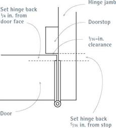
Leave a slight gap between the door and the doorstop, so the door won’t bind.

As you transfer the outline of this template to the face of the door, subtract V8 in. from the top and sides of the template to create an V8-in. clearance between the door and the jambs; subtract 74 in. from the bottom edge of the template for clearance above the finish floor or threshold. If the floor isn’t level, you may need more clearance. Place a 4-ft. spirit level across the opening to see how much out of level the floor is.

Trimming the Door

Trim the door rails of the door, then the stiles.

To prevent splintering, first score along cut-lines with a utility knife (see the photo on p. 96). Then use a 7‘A-in circular saw with a sharp, 40-tooth carbide blade to make the cut. For best results, cut V/i6 in. beyond the cut-line. Then use a belt sander with 80-grit sandpaper to trim the edge exactly to the cut-line. Some carpenters instead trim door edges with a handplane or power plane. If you use a power plane, go slowly to remove the wood gradually, making several shallow passes.

Cutting the Hinge Gains

Cutting hinge gains (recesses) is best done with a router and a template (see the photo on p. 103), but a hammer and chisel are easy enough if you’re hang­ing just one door. If the door frame already has hinge gains, transfer their locations to the door; otherwise, mortise the hinge gains into the door before trans­ferring hinge marks to the frame. To transfer hinge locations, use shims to position the door snug against the hinge jamb—with an %-in. gap. Then use a utility knife to mark the top and bottom of the hinge leaves in both the frame and the door.

Typically, the top of the top hinge is 7 in. from the top of the door; the bottom of the bottom hinge,

9 in. to 11 in. from the bottom of the door (see "Positioning Door Hardware," on p. 93). If there’s a third hinge, it’s equidistant from the other two.

Pull the hinge pins so you can work with one hinge leaf at a time. Set the hinge leaf slightly back from the edge of the door, as shown in "Hinge Setbacks." The setback from the hinge to the doorstop should be slightly greater than that from the hinge to the edge of the door, so there is room for several coats of paint. Use a combination
Подпись: Water-Return Threshold
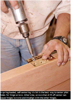
Подпись: A spring-loaded, self-centering Vix bit is the best way to center pilot holes for hinge screws. Otherwise, screws that drift off-center can cause hinges to twist and misalign with the other hinges.

image240

square to mark setback lines on doors and jambs. Finally, when mortising hinges, it’s best to set the router slightly shallow and then use a chisel to pare away the last little bit of wood so the hinge leaf is just flush. Setting hinges too deep can cause the door to bind.

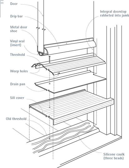
Подпись: This three-piece threshold fits over an existing threshold and can withstand just about anything short of Noah's Flood. For success, carefully fit and caulk the unit's pieces.Hanging the Door

Screw down all the hinge leaves using a self­centering Vix-bit®, which centers screws perfectly in the hinge holes. Then lift the door into the frame and mate the door’s hinge leaves with those on the frame, starting with the top hinge. Insert the hinge pins loosely, then eyeball the hinges as you open and shut the door. If the clearance between the door and the hinge jamb is excessive, remove the door and set the hinges a little deeper.
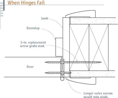
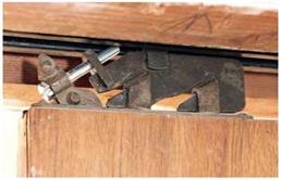
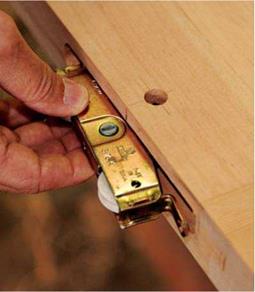
image241Подпись: Top-mounted pocket door mechanisms need oiling and a little ingenuity to keep them rolling. Here, an installer retrofitted a new machine bolt, sawing a slot into its head so the bolt can be easily turned to raise or lower the door.image242Подпись:image243

Replacing a short hinge-screw with one long enough to grab the framing should be your first “cure" when hinge leaves pull free from door jambs.

threshold and the drain pan, shut the door and spread a scriber to the distance from the top of the sill cover to the mark(s) on the jambs. Then scribe the bottom of the door to indicate the amount that you’ll need to trim off. Cut down the door, vacuum the existing threshold well, apply three beads of silicone caulking across the open­ing, and press the sill cover into it. Then do the same with the sill drain pan. Also caulk the jamb – and-pan joints. Finally, screw down the threshold and install the shoe on the bottom of the door, as described in the preceding section.

Multivariate Probability Distributions

Multivariate probability distributions are extensions of univariate probability distributions that jointly account for more than one random variable. Bivari­ate and trivariate distributions are special cases where two and three random variables, respectively, are involved. The fundamental basis of multivariate probability distributions is described in Sec. 2.3.2. In general, the availability of multivariate distribution models is significantly less than that for univari­ate cases. Owing to their frequent use in multivariate modeling and reliabil­ity analysis, two multivariate distributions, namely, multivariate normal and multivariate lognormal, are presented in this section. Treatments of some mul­tivariate nonnormal random variables are described in Secs. 4.5 and 7.5. For other types of multivariate distributions, readers are referred to Johnson and Kotz (1976) and Johnson (1987).

Several ways can be used to construct a multivariate distribution (Johnson and Kotz, 1976; Hutchinson and Lai, 1990). Based on the joint distribution dis­cussed in Sec. 2.2.2, the straightforward way of deriving a joint PDF involving K multivariate random variables is to extend Eq. (2.19) as

f x(x) = f 1(X1) X f 2(X2 | X1) X—X fK(X1, X2, . . ., Xk-1) (2.105)

in which x = (x1, x2,…, xK)t is a vector containing variates of K random vari­ables with the superscript t indicating the transpose of a matrix or vector. Ap­plying Eq. (2.105) requires knowledge of the conditional PDFs of the random variables, which may not be easily obtainable.

One simple way of constructing ajoint PDF of two random variables is by mix­ing. Morgenstern (1956) suggested that the joint CDF of two random variables could be formulated, according to their respective marginal CDFs, as

F 1,2(xb x2) = Fhx1)F2(x2){1 + в[1 – F 1(x1)][1 – F2(x2)]} for -1 < в < 1

(2.106)

in which Fk(xk) is the marginal CDF of the random variable Xk, and в is a weighting constant. When the two random variables are independent, the weighting constant в = 0. Furthermore, the sign of в indicates the positive­ness or negativeness of the correlation between the two random variables. This equation was later extended by Farlie (1960) to

F1,2(xb x2) = F1U1)F2(x2)[1 + ef 1U1)f2(x2)] for-1 < в < 1 (2.107)

in which fk (xk) is the marginal PDF of the random variable Xk. Once the joint CDF is obtained, the joint PDF can be derived according to Eq. (2.15a).

Constructing a bivariate PDF by the mixing technique is simple because it only requires knowledge about the marginal distributions of the involved random variables. However, it should be pointed out that the joint distribu­tion obtained from Eq. (2.106) or Eq. (2.107) does not necessarily cover the entire range of the correlation coefficient [-1, 1] for the two random variables under consideration. This is illustrated in Example 2.20. Liu and Der Kiureghian (1986) derived the range of the valid correlation coefficient value for the bivariate distribution by mixing, according to Eq. (2.106), from various combinations of marginal PDFs, and the results are shown in Table 2.4.

Nataf (1962), Mardia (1970a, 1970b), and Vale and Maurelli (1983) proposed other ways to construct a bivariate distribution for any pair of random variables. This was done by finding the transforms Zk = t(Xk), for k = 1, 2, such that Z1 and Z2 are standard normal random variables. Then a bivariate normal distri­bution is ascribed to Z1 and Z2. One such transformation is zk = Ф-1[^(xk)], for k = 1, 2. A detailed description of such a normal transformation is given in Sec. 4.5.3.

Example 2.20 Consider two correlated random variables X and Y, each ofwhich has a marginal PDF of an exponential distribution type as

fx(x) = e—x for x > 0 fy(y) = e—y for y > 0

To derive a joint distribution for X and Y, one could apply the Morgenstern formula. The marginal CDFs of Xand Y can be obtained easily as

Fx(x) = 1 — e—x for x > 0 Fy(y) = 1 — e—y for y > 0

According to Eq. (2.106), the joint CDF of X and Y can be expressed as

Fx, y(x, y) = (1 — e—x)(1 — e—y )(1 + вe—x—y) for x, y > 0

Then the joint PDF of X and Y can be obtained, according to Eq. (2.7a), as

fx, y(x, y) = e—x—y [1 + в(2e—x — 1)(2e—y — 1)] for x, y > 0

TABLE 2.4 Valid Range of Correlation Coefficients for the Bivariate Distribution Using the Morgenstern Formula

Marginal

distribution

N

U

SE

SR

T1L

T1S

LN

GM

T2L

T3S

N

0.318

U

0.326

0.333

SE

0.282

0.289

0.25

SR

0.316

0.324

0.28

0.314

T1L

0.305

0.312

0.27

0.303

0.292

T1S

0.305

0.312

0.27

0.303

0.292

0.292

LN

<0.318

<0.326

<0.282

<0.316

<0.305

<0.305

<0.318

GM

<0.318

<0.326

<0.282

<0.316

<0.305

<0.305

<0.318

<0.381

T2L

<0.305

<0.312

<0.270

<0.303

< 0.292

< 0.292

<0.305

<0.305

< 0.292

T3S

<0.305

<0.312

<0.270

<0.303

< 0.292

< 0.292

<0.305

<0.305

< 0.292

< 0.292

NOTE: N = normal; U = uniform; SE = shifted exponential; SR = shifted Rayleigh; T1L = type Ilargest value; T1S = type I smallest value; LN = lognormal; GM = gamma; T2L = type II largest value; T3S = type III smallest value. SOURCE : After Lin and Der Kiureghian (1986).

To compute the correlation coefficient between X and Y, one first computes the covari­ance of X and Y as Cov( X, Y) = E (XY) – E (X) E (Y ),in which E (XY) is computed by

f ж f ж a

E (XY) = xyfx, y(x, y) dxdy = 1 +-

J0 J0 4

Referring to Eq. (2.79), since the exponential random variables X and Y currently considered are the special cases of в = 1, therefore, xx = Xy = 1 and ax = ay = 1. Conse­quently, the covariance of X and Y is 0/4, and the corresponding correlation coefficient is 0/4. Note that the weighing constant 0 lies between [-1, 1]. The preceding bivariate exponential distribution obtained from the Morgenstern formula could only be valid for X and Y having a correlation coefficient in the range [-1/4, 1/4].

Energy Retrofits of All Levels

Paul Eldrenkamp is a Massachusetts remod­eler who has performed several deep-energy retrofits. When his clients balk at the high cost of a full retrofit, he sometimes advises them to work in phases. Although it is com­mon to perform energy improvements over time as finances permit, it’s also important to take advantage of upgrade opportunities even if they seem to fall out of sequence. For example, if you have to install new siding or roofing and you do so without installing thick rigid foam underneath, you may regret your shortsighted decision in time. Here’s a general overview of the work to be done, the order in which it should be completed, and the practical alternatives to going deep.

ROOF INSULATION

Deep-energy retrofit Many deep-energy retrofits call for insulating a roof to R-60, which can most easily be done by adding 4 in. of rigid polyisocyanurate foam on top of the roof deck and then filling each rafter bay with loose fill or batt insulation. Exte­rior foam sheathing has the added benefit of reducing thermal bridging through the rafters.

Practical approach It’s much less expensive to install cellulose on an attic floor than to install rigid foam and new roofing. Address air leakage before dragging a cellulose hose into the attic. Seal all ceiling leaks under the existing insulation (for example, at electrical and plumbing penetrations, at utility chases, and at the gaps between partition drywall and partition top plates). It’s also important to be sure that there are no air leaks at the perimeter of the attic, where the ceiling air barrier meets the wall air barrier.

Performance comparison While there is no upper limit on the R-value that can be achieved when installing foam on top of the roof sheathing, the maximum R-value of attic-floor insulation depends on the available height at the perimeter of the attic. Achieving R-60 requires about 16 in. of cellulose.

Cost comparison Attics with easy access are easier and cheaper to retrofit than cluttered attics with lots of penetrations that need to be sealed. From a material standpoint, the practical approach is almost always more economical. For any given R-value, poly- isocyanurate costs from three to five times as much as cellulose insulation. Needless to say, adding rigid foam on top of the roof sheathing includes significant expenses for roof demolition, new roof sheathing, and new roofing—costing between $3 and $5.80 per sq. ft.

BASEMENT INSULATION

Deep-energy retrofit After addressing any moisture issues in the basement, many deep – energy retrofits call for basement walls to be insulated to R-20, requiring the addition of 4 in. of XPS insulation or about 3 in. of

Pile it on. If adding rigid foam on top of the roof sheathing isn’t an option, a less expen­sive option is blowing cellulose on an air-sealed attic floor. The more insulation, the better.

Energy Retrofits of All LevelsПодпись:
Energy Retrofits of All LevelsПодпись: closed-cell spray polyurethane foam. The rim joists are also insulated with either spray foam or rigid foam. The basement floor is insulated with 2 in. to 4 in. of XPS foam over the slab. A new subfloor is applied over the foam. Practical approach Adding insulation to the basement walls and rim joists is cost effective in all northern climates. However, the payback period for basement-floor insulation is much longer than for basement- wall and rim-joist insulation, so it's often eliminated in projects with a limited budget. Performance comparison Since the tem-perature of the soil under a below-grade slab is higher than the average outdoor-air temperature in winter, heat loss through a basement slab is much less than through a basement wall. In many homes, basement slabs are responsible for less than 1% of a home's total heat loss. Cost comparison Not insulating your base-ment floor saves you from $1.80 to $2.50 per sq. ft. in materials. Подпись: cost: $140K annual savings: $2,300 While planning a deep-energy retrofit of his 3,000-sq.-ft. two- story duplex in Arlington, Mass., owner Alex Cheimets got a lucky break: He was eligible to participate in a pilot superinsulation program sponsored by the Massachusetts Department of Energy Resources and his local utility.

Water in the Pavement Surfacing

Andrew Dawson[7], Niki Kringos, Tom Scarpas and Primoz Pavsic

Abstract Pavement surfaces provide a key route of ingress of rain water into the pavement construction. Thus, permeability of asphaltic materials and the water ingress capacity of cracks in the pavement are very important. A range of equipment exists to determine the permeability of asphaltic mixtures both by in-situ and labo­ratory testing. Sometimes porous asphalt surfacing is provided to deliberately allow water into the pavement to limit spray from vehicles and to limit tyre-pavement noise generation. These porous surfaces can become clogged with fines, but reha­bilitating without causing premature damage is a challenge. Except for this planned acceptance of water into the pavement, water is generally undesirable as it often causes ravelling (stripping) of the asphalt whereby aggregate and binder separate. The mechanisms behind this separation are becoming better understood due to ad­vances in computational engineering and mechanical and physio-chemical testing.

Keywords Asphalt ■ cracking ■ infiltration ■ stripping ■ ravelling ■ porous asphalt ■ permeability

5.1 Introduction

The topmost layer of most pavements is comprised of a bound layer. The vast major­ity of pavements have an asphaltic surface. A far lower proportion have a Portland cement concrete (PCC) surfacing. Whilst it is usually a design aim of these surfaces that they provide an impermeable covering to all the lower pavement layers, water does penetrate such surfacings. It may do so either through intact, but not imperme­able, bound material or through cracks and joints in the surfacing. Although the em­phasis of this book is on water movement and its impact in the unbound material and subgrade layers of the pavement, some information on the movement and response in the upper, bound layers is indispensable. Apart from any other consideration, any
complete analysis of water in the road and foundation structure must consider the input conditions – which are significantly affected, perhaps even controlled, by the surface layer. In this chapter the emphasis is on asphaltic mixtures, their permeabil­ity and the damage that they suffer from water. Consideration is also given to the ingress of water through joints and cracks. Some of this may also be applicable to the ingress through construction joints and cracks in Portland concrete surfacings. In addition, some consideration is given to porous asphalt mixtures – surfacing that is designed to prevent runoff flowing over the surface.

Deflection

Deflection is similar to bending… but different. Bending concerns us most when it translates into bending failure, which is a bad thing. With deflection, we can tolerate certain amounts of it in certain circumstances. Springiness — or stiffness — in a floor is a characteristic of deflection. Cracking plaster on a ceiling, or separation of taped sheetrock joints, is an indication of excessive deflection.

Deflection is commonly expressed as a percentage or fraction of the span. Two common fractions you will encounter in span tables are V240 and V360 of a span. If a floor sags one inch over 240 inches (20 feet or 6 meters), this is a deflection of V240. A half-inch sag in 180 inches (15 feet or 4.6 meters) is an example of a deflection of V360. Charles Wing, author of several good books on homebuilding and sometimes called the father of the modern owner-builder movement, likes the V360 rule for first floors, where, normally, you don’t want to experience too much springiness.

There are also “rules” for ceilings. If you are supporting a plaster ceiling, deflection should be no greater than V360. With gypsum board, taping, and spackling, you can get by with V240 deflection. For roof rafters, a deflection of V180 is normally allowable by code.

Personally, I don’t use plaster or plasterboard ceilings, and I seldom use any kind of span greater than ten feet, because I put heavy earth roofs on almost every building I’m involved with. So, deflection has never been a big issue. With exposed plank ceilings, V180 of deflection would be fine for roof rafters, and V240 would certainly be acceptable for any floor with a wood ceiling beneath it.

Normally, if a floor joist or roof rafter plan meets the criteria for allowable loads on bending, it will be fine on deflection. Simply use commonly available span tables. I have included examples of some basic span tables in Appendix A, and also a list of where more comprehensive tables can be found. Here is just one example, to give you an idea of the kinds of dimensions we’re talking about, and I get this right out of the new International Residential Code for One – and Two – Family Dwellings, Table R502.3.1(2), a portion of which is reproduced in Appendix A. We assume that this is a residential living area with a live load of 40 pounds per square foot (PSF), a dead load (structural load) of 10 PSF and an allowable deflection of V360. Using Douglas Fir-Larch #1, and with joists 16 inches on center, a two-by-eight can span 13 feet 1 inch (3.99 meters). With two – by-tens, the allowable span increases to 16 feet 5 inches (5.0 meters). With a lesser quality of wood, such as #2 Southern Pine, the allowable spans drop to 12 feet 3 inches (3.12 meters) for two-by-eights and 15 feet 5 inches (4.7 meters) for two-by – tens. For residential sleeping areas, where loads of 30 pounds per square foot is assumed, allowable spans are greater. Find these figures in Appendix A, Table 1, and you will be well on your way to being able to use span tables.

Also in Appendix A, there are two examples of using a rafter span table with a 70-pound snow load and a 20- pound dead load. Back to posts…

Подпись:We do not normally think of vertical members, such as posts or even trees, as being beams, but, in fact, they share a lot in common with beams.

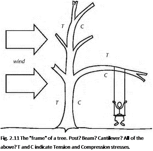
The word “beam” even comes from an old English word meaning tree or tree trunk. When a tree is being blown by the wind, the windward side is in tension as the tree bends away from the wind. The leeward side is in compression. Actually, as the tree is unsupported at the top, it can be thought of as a cantilever, just another kind of beam. A tree branch, extending out from the trunk, is a cantilever built out from a cantilever. We’ll speak more of cantilevers in a moment.

In “post and beam” construction, the posts are the naturally strong component, because they are extremely strong on compression. For example, a six-by-six of a relatively low compressive strength of 1,150 to 1,400 inch-pounds per square inch (you don’t really have to know what this unit means to get the point here; I certainly don’t) will support 32,800 pounds at eight feet of height. That’s 16.4 tons! An eight-by-eight of the same quality will support 63,000 pounds, 31.5 tons.

Tons, I understand. Even with our two stories and heavy earth roof, five of the seven major eight-by-eight posts at Earthwood support about 10,000 pounds each and the other two (full-sized eight-by-eight solid oak) support only 15,000 each, way under their capacity. (An oak eight-by-eight is good for over 93,000 pounds at eight feet of height.) In short, the post part of “post and beam” framing is very strong.

Four-by-fours would actually do for five of the seven posts at Earthwood if it weren’t for our esthetic sensibilities and something called “slenderness ratio” or SR. Visually, a four-by-four supporting an eight-by-eight or ten-by-ten girder just doesn’t look right, like a four-by-eight rafter laid the wrong edge down. But, structurally, the four-by-four post would probably do the job.

“Slenderness ratio” is simply the relationship of the width of the post its length. A 96-inch (8-foot or 2.44-meter high) post that is only four inches wide on its narrowest dimension has an SR of 96 inches/ 4 inches, or 24. Put an eight-by-eight there, and the SR becomes 96 inches/ 8 inches, or 12. The higher the number, the weaker the post. A slender post is much more subject to buckling than compression failure. Lets say we had a four-by-four supporting a heavy load as a post, and that there was a large knot on one or more edges of the post. While knots can be fairly strong in compression, they are weak in tension, as they tend to separate easily from the surrounding wood. A lateral load, such as a sudden impact, or the oscillation during an earthquake, could easily cause such a post to buckle and fail. Extreme vertical loads could do it, as well.

Recent Research

Researchers interested in frost action in soils agree on the description illustrated in Fig. 4.3 on how ice lenses grow and cause frost heave. Nevertheless, when it
comes to the degree of water saturation of the unfrozen soil below the freezing front there are two different conceptions. Some researchers believe that the un­frozen soil is fully saturated while others believe it is unsaturated. Of course, these discrepancies in understanding lead to different explanations of the driving force of the capillary rise of water as well as different opinions on how to run laboratory experiments. Andersland and Ladanyi (2004), for example, Konrad and Morgenstern (1980) and Nixon (1991) give equations where it is obvious that full saturation is assumed for the unfrozen soil. Accordingly, Konrad (1990) refers to experiments where the specimen freezes from below and free access to water is permitted at the top. This, of course, gives full saturation of the unfrozen soil. In contrast to this view, Miller (1980) discusses frost heave as freezing of unsaturated soil and references experiments where water is fed in at the bottom of the specimen and ice lenses are fed through capillary rise in unsaturated soil. Accordingly, Penner (1957) freezes unsaturated soil and Hermansson and Guthrie (2005) present laboratory ex­periments where freezing and frost heave takes place at a height more than 0.5 m above the level of the water supply. It should also be noted that Hermansson and Guthrie (2005) describe testing where the specimen heaves significantly without addition of any external water at all. This, of course, contradicts the assumption that the soil below the freezing front is fully saturated. The expansion without addition of water is suggested to be an effect of air entering the soil.

In agreement with the laboratory experiments Hermansson (2004) described a field study where the depth to the groundwater table is 6 m. Under such a thoroughly drained condition, it is reasonable to assume that the soil is far from saturated. De­spite this Hermansson reported 80 mm of frost heaving over a period of 2 months.

The conclusions from these studies are twofold,

• Firstly, frost heave does not require full saturation; and

• Secondly, even a well drained soil might experience a significant frost heave.

In addition to the different understandings about the importance of saturation, there are also two different schools when proposing equations to describe frost heave (Hansson, 2005). One school neglects the liquid water pressure and the other one neglects ice pressure. The first school, characterised by “Miller-type” models, de­velops models describing the frost heave on a microscopic scale while the second school, characterised by “hydrodynamic” models, handles equations for the redis­tribution of water up to the freezing front, supplying the frost heave. No computer code is known that handles both processes realistically.

3.5 Conclusions

Heat transfer in soils involves convection, radiation, vapour diffusion and con­duction. For pavements, conduction is the most important factor. During warm and sunny summer days though, natural convection should not be neglected. The heat transfer is closely associated with water movements – evaporation pulls water through the soil to the evaporation surface. Freezing also drives water movement as water is drawn to the freezing front in soils which have moderate pore sizes and moderate permeability.

Frost susceptible soils always experience frost heave at freezing even if there is no saturation. Drains will lower the heave by reducing the water content but a frost susceptible soil will always hold enough water for a significant heave. Chapter 13 describes some drainage techniques that can help to address these prob­lems. Interested readers are also directed to the reports on frost and drainage, mostly in the context of seasonally frost affected roads, available from the ROADEX project (Berntsen & Saarenketo, 2005; Saarenketo & Aho, 2005).

Ice Lenses

Frost heaving of soil is caused by crystallization of ice within the larger soil voids. Ice lenses attract water to themselves by the, so-called, cryo-suction process, and grow in thickness in the direction of heat transfer until the water supply is depleted or until freezing conditions at the freezing interface no longer support further crys­tallization, see Fig. 4.3. As the freezing front penetrates deeper into the pavement, the growth of ice lenses ceases at the previous level and commences at the new level of the freezing front. At some point the heat flow will be reduced so that further freezing slows or the weight of overlying construction will impose sufficient stress to prevent further ice lens growth.

Fundamentally, the so-called cryo-suction process results from the consequences of the phase change of pore water into pore ice and the associated energy changes in the remaining pore water. As water arrives at the point of freezing, the soil skeleton expands to accommodate it while consolidation of the adjacent, unfrozen, soil may occur as water is pulled from that. The particular characteristics of the process are strongly affected by soil porosity, soil-water chemistry, stress conditions at the point of ice formation, temperature, temperature gradients in the adjacent soil(s), water availability, etc. Coussy (2005) gives a more detailed outline of the mass flow and heat flow elements that combine in the processes that are active at the freezing front.

Ice Lenses

Capillary water is crucial for frost heaving. The pavement damage range depends on the rapidity of freezing, i. e. if freezing occurs rapidly, ice lenses are distributed over a greater mass of soil, which is somewhat more favourable compared to slow freezing where the capillary inflow of water will cause a high concentration of ice lenses. Frost heave primarily occurs in soils containing fine particles (i. e. frost – susceptible soils). Clean sands and gravel are non-frost susceptible because they cannot hold significant pore suctions, so water cannot be drawn to the freezing front through them. Silty soils represent the greatest problem. For even finer soils, like clays, the pores are very small. These small pores lead to a low coefficient of per­meability which does not allow water to travel through the pores at a speed that would allow a fast capillary rise, hence ice lens formation is less.

The Payback

Homeowners who undertake deep-energy retrofits are usually motivated by environ­mental or energy-security concerns rather than a desire to save money on their energy bills. These jobs are so expensive—in the range of $50,000 to $150,000 per house— that a homeowner would have to wait decades before the investment could be recouped. "In a retrofit situation, it can cost a lot of money to save a small amount of en­ergy," says energy consultant Michael Blas – nik. "Going from R-19 to R-40 walls or R-30 to R-60 ceilings doesn’t save a whole lot of Btu—and the cost of that work is potentially tremendous."

There’s no easy way to calculate the payback period for many deep-energy ret­rofits, in part because a major overhaul of a building’s shell inevitably includes many measures (for example, adding new siding or roofing) that aren’t energy-related. Although these elements don’t make a significant con-

tribution to a home’s energy performance, they may greatly enhance the home’s aes­thetics and value.

Those of us without a Midas budget will need to settle on a less ambitious approach to energy savings than a full-blown deep – energy retrofit, and that’s OK. Less expensive and less invasive retrofit measures, typically referred to in the industry as weatherization, have payback periods of 15 years or less.

Physics of Frost Heave

3.4.1 Frost Heave and Spring Thaw

Frost heave occurs in roads having fine graded, so-called frost-susceptible, mate­rial, at a depth to which the freezing front reaches during the winter. A well-built road of consistent materials and cross-section can be expected to heave relatively evenly. When inconsistencies or inhomogeneities are found in the construction of the affected subgrade, then frost heave is likely to be uneven and may well cause an uneven road surface that results in reduced travelling speed and comfort.

Although such heave can be problematic, a much greater problem usually arises in spring-time when the ice that has formed in the road construction, which was instrumental in causing the frost heave, melts and results in a very high water content in the pavement and subgrade. The increased water content often means reduced bearing capacity. For this reason many countries impose spring-thaw load restrictions on low volume roads to avoid severe pavement deterioration.

STEP 2 PLATE THE WALLS

This step involves laying out all of the lumber required for the top and bottom plates, cutting the plates to length, and temporarily tacking them on their layout lines so that matching marks can be made on both plates for the studs, doorways, windows, and intersecting walls. Don’t plate, mark, and build one wall at a time. This old method is time-consuming and makes it difficult to frame accurately. Instead, put all the plates down for every wall, beginning with the outside walls.

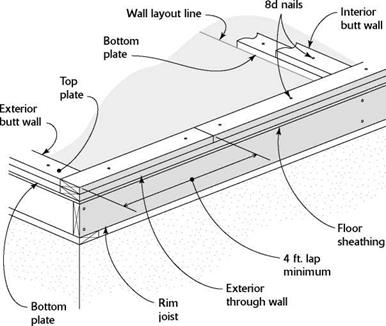
It’s best to plate the long, outside through walls first, then plate the outside butt walls that extend between the through walls. As shown in the illustration on the facing page, through walls have plates that run through from corner to corner. Walls that fit between or intersect other walls are called butt walls. After you

• Plate exterior walls first, beginning with through walls.

• Plate interior butt walls second.

• Use 8d nails to temporarily tack plates in place.

Подпись: “Tacking” is temporary. When a framing carpenter uses the word “tack,” it means that parts are temporarily nailed together.When possible, tack top plates directly on top of bottom plates.
STEP 2 PLATE THE WALLSSelect straight plates. Check 2x plate lumber for bow and twist and select only the straightest boards for plates. This makes for strong, straight walls.
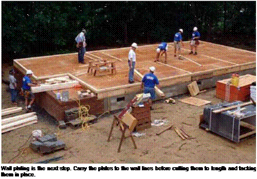
Подпись: Wall plating is the next step. Carry the plates to the wall lines before cutting them to length and tacking them in place.

finish plating the outside walls, you can move inside, beginning with the longest walls and working your way toward the shortest ones.

Stack, tack, and cut

Plating a wall involves three procedures. STACK THE PLATES. Place two layers of plate stock (2x4s are used for the wall framing on this house) along the layout line for the wall. These layers will become the top and bottom plates. Reserve the straightest 2 x4s for the plates, and use the longest plates (typically 16 ft.) on the longest exterior walls. Pay attention to where the top plate stock butts together. These butt joints should be at least 4 ft. away from an intersecting wall.

TACK THE PLATES IN PLACE. After you’ve distributed the plate stock, you can start tacking it down. Using 8d nails, tack, or

Подпись: Top plateSTEP 2 PLATE THE WALLSПодпись:STEP 2 PLATE THE WALLSПодпись:STEP 2 PLATE THE WALLSПодпись:

Most walls are plated this way. The bottom plate is tacked to the floor and the second plate is tacked to the first with 8d nails.

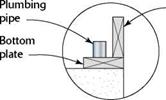
Two ways to plate walls that house pipes

STEP 2 PLATE THE WALLS

temporarily nail, the bottom plate to the sub­floor right on the line. Drive an 8d nail about 1 ft. from the end of each board and another near each intersecting wall. Tack the top plate directly on top of the bottom plate. Continue stacking and tacking until you reach the end of the wall.

CUT THE PLATES TO LENGTH. As you’re stacking and tacking, you’ll also be cutting plates to length with a circular saw. Where 2x plate stock butts together, make sure that the ends are square-cut and that they meet snugly. Although it’s acceptable for the bottom plate to be a little short, the top plate must be as close as possible to the exact length. The bottom plate of a framed wall is nailed to the subfloor. Roof trusses are nailed to the top plates.

When the outside walls have been plated, you can start scattering plate stock for the interior walls. Don’t do this haphazardly. Just as when you were laying out the walls, it’s best to plate the long, parallel interior walls first. These long walls become through walls into which shorter walls butt. Plate the shortest walls last. Pay attention to which interior walls are butt walls and which ones are through walls. If the walls are plated properly, it is easier to build and raise them. I run all plates continuously, ignoring door and window open­ings. The bottom plate will be cut for the door openings later.