Plumbing Tools

A level is the traditional tool for determining plumb. A laser can also be used. Whichever tool you use, you want to make sure you check it for true before you start. To check a level, hold it in position against a wall and read the bubble. Then turn it around and place it in the same position against the wall. If the bubble reads the same, then your level is accurate.

To check a laser use a similar method. Set it in place, and mark the bottom dot and the top dot. Then turn it around and align the bottom dot. If the top dot hits the same spot on the top of the wall that you marked, your laser is reading accurately.

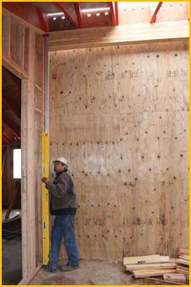
Levels are accurate when the level is long enough to reach from the bottom plate to the top plate. An 8′ level will work fine for most residential walls. A 12′ extension level works for walls up to 12′. If the level does not reach from plate to plate, you have to figure that there will be some variance for the studs’ irregularities.

Plumbing ToolsПодпись: Plumbing tall wall with extending level.Lasers are good for taller walls. Lasers are not dependent on perfect wood for determining plumb. Set the laser at the bottom, and read the distance you set at the bottom on your tap at the top of the wall. If you need to check plumb on a regular basis, the laser has the advantage of fitting in your pouch.

INSTALLING THE WINDOW UNIT

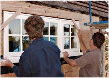
Before installing window units, remove the packaging, shipping blocks, screens, storm windows, and so on. If the unit is uncased, screw temporary cleats to the outside edges of the frame so that when it is placed in the opening, its jamb edges will be flush to the sheathing. Window installation is a two-person job—one inside, one outside.

1. Dry – fit the window first.

Set the bottom of unit onto the RO sill and tilt the window up into place. There should be roughly h in. of space on both sides of the unit and h in. to 1 in. above. Using a spirit level, the person outside quickly checks for level and plumb. If there are no glar­ing problems, set the unit aside and caulk around the opening.

2. Caulking details will vary. For most pre­cased or flanged units, apply a continuous 18-in. bead of siliconized acrylic caulk along the sides and top of the RO, back h in. from the edge, and press the casing or flange of the new unit into the caulking for a good seal. If the unit is uncased, caulk only along the bottom of the opening, at this stage.

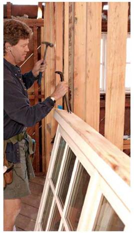
3. Now install the window. As the outside person supports the unit, the inside person uses a small flat bar inserted between the RO and the frame to center the unit in the opening. That done, the person outside uses a spirit level to check the window’s sill and head for level, while the person inside uses the flat bar and adds shims as needed. Once the unit is level and plumb, the outside person uses a tape measure to check the frame’s “diagonals” (opposite corners of the frame). If diagonal measurements are equal, the frame is square.

4. When the unit is level and plumb, nail the upper corners of precased units and units with nailing fins. Tack uncased units with a nail or screw centered in each side jamb, down about 4 in. from the top of the frame. Open and close the window to see if it binds. Where the frame binds, use screws to draw it out or shims to push it into the opening. If you are installing a double – hung window, make sure the meeting rails meet evenly.

image247

After dry-fitting the window, flash the sill of the RO and run a bead of siliconized acrylic latex caulk near the corner so the window seats in it. Once the window is in place, apply an additional bead of caulk to the underside of the windowsill to cut air infiltration.

Подпись: Once the unit is shimmed and screwed into final position and the window opens and closes freely, cut the shims flush with the inside face of the framing. Do the same outside. Подпись: After applying a bead of caulking along the outside edge of the jambs, seat fiber-reinforced flashing paper in the caulking, as shown. Apply a second bead of caulking over the paper. Then install the casing and head flashing as shown on p. 89. FINISHING TOUCHES

Use a Japanese saw or a utility knife to cut the shims flush to the interior finish surfaces and exterior sheathing. Set the nails or sink the screws holding the frame to the opening, and then fill the holes. Use a mild-expanding polyurethane spray-foam sealant to stop air infil­tration around the unit. This type of foam is less likely to bow window frames than a foam that expands aggressively (see Chapter 14).

Now weather-seal the outside of the opening.

If you installed a precased unit, it’s already set in caulking, so you’re ready to install the cap flash­ing. If the unit has continuous nailing flanges, seal the sides and sill with strips of self-adhering membrane. But install cap flashing before apply­ing a self-adhering membrane strip across the top of the unit.

If the unit is uncased, like the unit shown in the photos, caulk the side jamb edges with siliconized acrylic caulk (run the beads back h in. from jamb edges), press fiberglass-reinforced strip flashing into the caulk, and nail the side casing to the jambs, using 8d galvanized finish nails. Then apply a bead of caulking to the edge of the head jamb and nail up the head casing to the side cas­ings. To keep the joints from pulling apart, send one nail diagonally through each joint, too. Then apply the cap flashing (usually metal or vinyl), nailing through its top leg. Flashing strips, self­adhering membrane strips, or housewrap over­laps that top leg. Finally, apply a bead of surface caulk to the frame/sheathing joints all around.

Pavement Deterioration

Pavement deterioration or distress can be classified into two basic categories for all pave­ment types—structural and functional. The most serious category is structural. Structural deterioration results in reduced ability to carry load and a decreased pavement life. Functional deterioration can lead to and accelerate structural deterioration, but it is only related to ride quality and frictional characteristics. A third type is environmental deterioration, which is a form of material-related distress. Environmental deterioration affects pavement materials and will generally exhibit itself as either functional or structural deterioration.

Pavement Deterioration

log10 MR – 8.07


+ 2.32


Подпись: Reliability, R (%)

Pavement Deterioration

S0 = 0.35 MR = 5000 lb/in2 Д (lb/in2) 1.9 Solution: SN = 5.0

FIGURE 3.17 Design chart for flexible pavements based on using mean values for each variable. Conversions: 1 kip = 4448 N, 1 lb/in2 = 6.895 X 10⁻³ MPa, 1 kip/in2 = 6.895 MPa. {From Guide for Design of Pavement Structures, American Association of State Highway and Transportation Officials, Washington, D. C., 1993, with permission)

TABLE 3.25 Recommended m Values for Modifying Structural Layer Coefficients of Untreated Base and Subbase Materials in Flexible Pavements

Quality of drainage

Percent of time pavement structure is exposed to moisture levels approaching saturation

Less than 1%

1-5%

5-25%

Greater than 25%

Excellent

1.40-1.35

1.35-1.30

1.30-1.20

1.20

Good

1.35-1.25

1.25-1.15

1.15-1.00

1.00

Fair

1.25-1.15

1.15-1.05

1.00-0.80

0.80

Poor

1.15-1.05

1.05-0.80

0.80-0.60

0.60

Very poor

1.05-0.95

0.95-0.75

0.75-0.40

0.40

Source: Guide for Design of Pavement Structures, American Association

of State Highway and Transportation Officials, Washington, D. C., 1993, with permission.


Pavement Deterioration

FIGURE 3.18 Chart for estimating structural layer coefficient (a^ of dense-graded asphalt concrete based on the resilient modulus. Conversion: 1 lb/in2 = 6.895 X 10_3 MPa. (From Guide for Design of Pavement Structures, American Association of State Highway and Transportation Officials, Washington, D. C., 1993, with permission)


0.20

0.18

0.16

0.14

0.12

0.10

0.08

0.06

0.04


40 –


Pavement DeteriorationPavement DeteriorationPavement DeteriorationPavement Deterioration

Pavement Deterioration

(1) Scale derived by averaging correlations obtained from Illinois.

(2) Scale derived by averaging correlations obtained from California, New Mexico, and Wyoming.

(31 Scale derived by averaging correlations obtained from Texas

(4) Scale derived on NCHRP project.

FIGURE 3.19 Variation in granular base layer coefficient (a2) with various base strength parameters. Conversion: 1 lb/in2 = 6.895 X 10~3 MPa. (From Guide for Design of Pavement Structures, American Association of State Highway and Transportation Officials, Washington, D. C., 1993, with permission)

Pavement deterioration is an important measurement for a pavement engineer. To determine the remaining life of a pavement, or the amount of pavement repair required to extend a pavement life for a given time period, or the most appropriate time for pavement repair, the amount and type of deterioration in a pavement must be measured. Methods of measurement of pavement deterioration vary, but most are similar in that they all require a visual inspection of the pavement and a somewhat subjective distress rating.

Pavement Deterioration

FIGURE 3.20 Variation in granular base layer coefficient (a3) with various subbase strength parameters. Conversion: 1 lb/in2 = 6.895 X 10_3 MPa. (From Guide for Design of Pavement Structures, American Association of State Highway and Transportation Officials, Washington, D. C., 1993, with permission)

Installing a Basic Window

Some of the terminology for doors and door frames is common to windows and window frames. For example, frames are made of jambs, a head, and a sill, with stops to guide or seat win­dow sashes. Window sashes, like door frames, have horizontal rails and vertical stiles.

WINDOW CHOICES

Windows arrive installed in a preassembled frame, complete with the hardware necessary to operate them. Unlike door installation, there is no need to trim window jambs, so the sill is always preattached. You can order windows pre­cased (casing preattached), but such units can be tricky to shim properly. Uncased units are better suited to renovation: Local mills will offer a wider range of casings than window manufac­turers, and you’ll have more latitude in adjusting casings to irregular walls or out-of-square frames.

Wood windows are the sentimental favorite. They’re also pleasant to work with and good looking, but they take a lot of maintenance. On the other hand, vinyl-clad and aluminum-clad wood units are virtually maintenance-free, though they cost more. Of late, all-vinyl units have become popular, and are an especially good choice in rainy regions. Metal windows, on the other hand, seldom look good as retrofits in older houses; and because they encourage condensation and heat loss, they’re a poor choice in cold climates.

Clad window units come in a variety of durable prefinished colors, eliminating costly exterior painting. Many manufacturers will cus­tomize a range of factory-built window units to your specifications. Options include a choice of fixed, double-hung, single-hung, sliders, bow, bay, casement, awning, and hopper styles; single – or double-glazing; many configurations of lights and muntins; custom glass for sound or UV light attenuation; safety glass; custom jamb widths; extended sill horns to accommodate various exte­rior casing details; and mulled units (windows

Подпись: Sizing Windows Window catalogs list several dimensions for windows, including a callout size, which indicates the size of rough opening (RO) required, and a unit size, which denotes the outer dimensions (width and height) of the window frame. Window dimensions are stated as pairs of numbers; the first number is always width. Thus a window with a callout size of 4030 needs an RO 40 in. wide by 30 in. high. Typically, the unit size of a window (frame) is V/ in. less in height and width than the callout size, but always check manufacturer's specs to be sure. Note: Window sashes are usually 13/ in. thick unless otherwise noted. When ordering window units, measure the width of the ROs in three places from top to bottom and the height in three places from side to side. Window manufacturers usually prefer the smallest reading in each direction but, again, follow the manufacturer's ordering instructions to the letter. Also measure the thickness of the walls, from interior finish surfaces to exterior sheathing; you may need jamb extensions as well. Measure openings and order windows well in advance. If your window units are in odd sizes or otherwise unusual, they may require a special order, which could delay your job.

ganged together to create larger units). These factory-built wood windows are generally made to tighter tolerances than shopbuilt windows, ensuring good weather tightness and insulation values.

PREPPING THE OPENING

Before ordering windows and again just before installing them, check the ROs for level and plumb. Most window units will need some shim­ming, but if the sill is level, the rest of the instal­lation will be relatively easy. Typically, an RO is 1 in. taller and wider than the window frame.

WEATHERPROOFING OVERVIEW

Water is persistent, so always wrap exterior wall openings with moisture barriers before installing windows, and use cap flashing on the frame heads to direct water around the opening. The order in which you install weatherproofing mate­rials depends on several variables: Is exterior sheathing exposed or covered by building paper

image244

Before installing windows, carefully remove the packaging and shipping blocks.

and siding? And are window units uncased, pre­cased, or surrounded by a continuous nailing flange?

If the sheathing is exposed, run housewrap or building paper at least 4 in. into the RO, and staple it to the framing. However, leave the housewrap over the top of RO unstapled because it will overlap the window’s cap flashing later.

Alternatively, you can first flash the perimeter of the RO with strips of fiberglass-reinforced flashing or with self-adhering membrane. Self­adhering membrane is more expensive, so it’s often reserved for flashing sills and head casing, which are more likely to leak. Flash the sill first, folding the strip ends so they extend at least 6 in. up onto the jack studs. Then flash the jack studs, overlapping the upturned ends of sill flashing. (But don’t flash the head of the opening yet; that needs to wait till the window is installed.) Then run housewrap or building paper up to the edges of the opening, overlapping the strip flashing just installed.

If the exterior is already covered with building paper and siding, you’ll need to fit flashing strips and cap flashing under it. If there’s lap siding such as clapboards, or wood shingles, this is rela­tively easy: Drive a shingle ripper up under siding courses to cut the nails holding them, slide flash­ing strips under the existing building paper and siding, and then caulk and install the unit, as described in the next section. Cut siding nails back at least 4 in. around the opening, although you may want to cut back shingles 12 in., allow­ing you to offset the shingle joints correctly.

Подпись:Подпись: PROnP Windows are usually installed by setting the bottom onto the sill of the opening and tipping the unit up into place. But if you're installing a flanged unit, which has integral cap flashing, slip the cap flange up under the housewrap and siding first; then swing the bottom of the unit onto the sill. Obviously, you'll need to slit the housewrap or pry out the siding nails above the opening to insert the flange. 1111 Подпись: Dry-fit the window first to make sure it fits and that there's enough space in the opening to level and shim the unit. That done, set the window aside, and caulk around the opening. The temporary diagonal cleats at the upper corners keep the jambs flush to the sheathing.image246Replace and renail the siding, as necessary; then caulk and install the window as described in the next section.

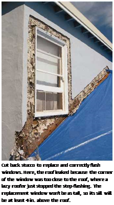
If there’s stucco, the only way to retrofit flash­ing successfully is to cut back the stucco and wire lath 6 in. to 8 in. around the opening, using an electric chipping hammer (see the top photo on p. 145). After installing the new unit, insert flash­ing beneath the existing building paper (especially the cap flashing), tie new wire to the old, and patch the stucco.

PAVEMENT MANAGEMENT

Project-level pavement management is responsible for continuous evaluation of pave­ment’s present serviceability, monitoring of the pavement loading rate, determination of the cause and rate of pavement deterioration, prediction of optimal time for inter­vention, and evaluation of the most economical rehabilitation strategy.

Pavement management can be applied at the project level or at the network level. Although both levels are very dependent upon one another, they are seldom applied for the same purpose. The network level applies to the whole system in a global sense. Network refers to systemwide averages and is used for system budgeting and performance modeling. This chapter addresses only the project-level aspects. Project-level pavement management is considered to be more complicated and more important than pavement design. Pavement management is applied throughout the life of a pavement, whereas pavement design is com­pleted and forgotten once the pavement is initially in service.

CARRYING LUMBER

Framing lumber can be heavy. A 2×4 stud isn’t a big deal, but a wet, 16-ft. 2×12 sure is—and there are many boards of that heft even in a small house. Don’t carry lumber by holding the board at your waist; this puts undue strain on your elbows and lower back. Instead, grab a long, heavy board at its balance point and, in one fluid motion, lift and flip it gently onto your shoulder. With your entire body helping absorb and distribute the weight, the load is much easier to carry.

Подпись: V ,

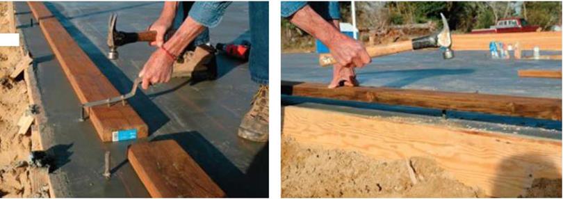
Another way to mark the plate is by creating indents of the bolts on the plate. Place the plate over the bolts and apply pressure. [Photo by Don Charles Blom]


Mark the sill plate on the slab with a bolt marker.

[Photo by Don Charles Blom]


Solidly brace the plate while drilling bolt holes with a spade bit. [Photo by Don Charles Blom]


The band joist is nailed on top of the plate. The floor joists are nailed to the band joists. [Photo by Don Charles Blom]


CARRYING LUMBERCARRYING LUMBER

Подпись: Add anchor bolts to slabs. Anchor bolts need to be within 1 ft. of the end of a wall plate. If necessary, additional bolts can be epoxied into holes drilled in the slab, or suitable masonry anchor bolts can be installed.

Plating on a concrete slab and around plumbing

Remember to use treated wood when working on concrete. Untreated wood placed next to a slab is an open invitation for hungry termites to move in. When working on a slab with anchor bolts, use an anchor-bolt marker to locate the holes in exterior wall plates (see p. 58 for more on anchor bolts). With a bit of practice, you can also mark the bolt holes by setting the plate di­
rectly on the bolts. Just sight down and align the plate edge with the chalkline, then hit the plate with a hammer directly over the bolts.

After the holes are drilled, you can fit the bottom plate on the anchor bolts and nail the top plate along the bottom plate’s outside edge (see the illustration on the facing page). It can also be toenailed on edge to the top of the top plate.

If you encounter plumbing pipes in the walls, cut the bottom plate to fit around them.

FLEXIBLE PAVEMENT DESIGN PROCEDURE

Д (Ib/in2) 4.5- 1.5

1.624* 107

18.42

(Ec/k)02

s’c* cd (d0-75- і. ізг|


FLEXIBLE PAVEMENT DESIGN PROCEDURE

+ (4.22- O.32pt)*log10


215.63 *J P0J5-


Подпись: 267
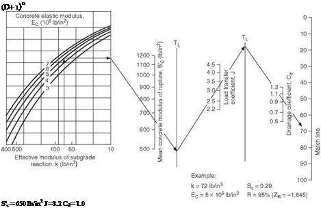
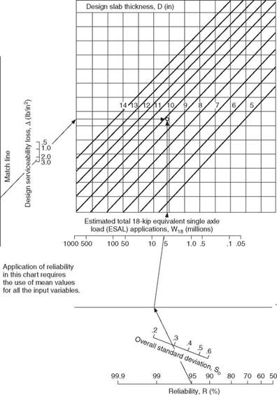
Подпись: (D+ 1)8 S'c = 650 Ib/in2 J =3.2 Cd= 1.0 Д (Ib/in2) = 4.2-2.5= 1.7 W18 = 5.1 x 10⁶ (18-kip ESAL) Solution: D = 10.0 in.

(nearest half-inch, from part b )

FIGURE 3.15 Design chart for rigid pavements based on using mean values for each input variable. Conversions: 1 lb/in2 = 6.895 X 10⁻³ MPa, 1 lb/in3 = 271.4 X 10⁻⁴ N/mm2, 1 in = 25.4 mm. (From Guide for Design of Pavement Structures, American Association of State Highway and Transportation Officials, Washington, D. C., 1993, with permission)

Подпись: LПодпись: FIGURE 3.15Подпись: (Continued)FLEXIBLE PAVEMENT DESIGN PROCEDURE

10­

Note:

FLEXIBLE PAVEMENT DESIGN PROCEDURE

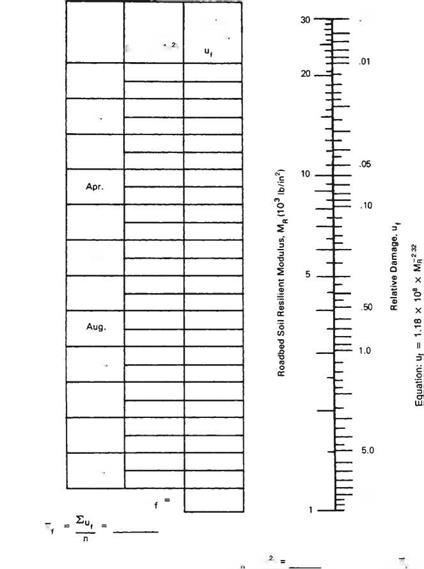
005


Relative

Damage


Month


Jan.


Feb


Mar.


May


June


July


Sept


Oct.


Nov.


Dec


10.0


Summation: Eu


13.0


Average: u


FLEXIBLE PAVEMENT DESIGN PROCEDURE

FLEXIBLE PAVEMENT DESIGN PROCEDURE

Подпись: (corresponds to ujEffective Roadbed Soil Resilient Modulus, M„ (Ib/in >

FIGURE 3.16 Chart for estimating effective roadbed soil resilient modulus for flexible pavements designed using the serviceability criteria. Conversion: 1 lb/in2 = 6.895 X 10_3 MPa. (From Guide for Design of Pavement Structures, American Association of State Highway and Transportation Officials, Washington, D. C., 1993, with permission)

Determine Pavement Structural Number. The flexible pavement process involves the calculation of a pavement structural number. This is an abstract number reflecting the relative strength contribution of all layers in the pavement buildup. The structural number SN is calculated using the design values determined as outlined above in the nomograph shown in Fig. 3.17. The design thickness for each layer is determined to satisfy the following equation:

SN = a1D1 + a2D2m2 + a3D3m3

where a1, a2, a3 = structural coefficients of surface, base, and subbase, respectively

D1, D2, D3 = thickness of surface, base, and subbase, respectively, in m2, m3 = drainage coefficients for base and subbase (see Table 3.25)

The structural coefficients of the asphalt layer, granular base, and subbase can be esti­mated using Figs. 3.18, 3.19, and 3.20, respectively, or can be estimated from Table 3.26.

Select Layer Material and Thickness. Once the structural coefficients are known, the thickness of the individual layers is determined by varying D1, D2, and D3 until the calcu­lated SN is equal to or greater than the required SN. Unbound bases are commonly speci­fied to the nearest 1 in (25 mm), and asphalt concrete is normally specified to the nearest 1/4 in (6 mm). The procedure shown in Fig. 3.21 illustrates one method recommended for determining layer thickness. This procedure designs the upper layers to protect the lower layers.

Concrete Curing

After pouring, concrete can cure and gain strength only if it remains nearly saturated with water for a minimum of 28 days. The cur­ing process stops if the relative humidity of the concrete drops below 80 percent Improp­erly cured concrete will develop structural weaknesses and cracks that can become path­ways for unwanted moisture and soil gases to creep into the building. Rushing the drying process may also weaken the surface so that concrete dust continually sloughs from the surface into the home. Pouring slabs in cold weather is also risky since cold temperatures impede the curing process. The use of propane heaters may cause the concrete surface to be­come weak and crack as combustion gases en­ter the material and interfere with its chemical composition.

Improperly cured concrete will have high alkalinity levels that can cause certain sub­strates and finishing materials to breakdown or rot. Testing pH can help determine whether a concrete surface has been properly cured and whether problems will develop with cer­tain finish applications. This simple test is described in the materials testing section of Division 13.

Determine dimensions for stud length and header height

Stud length, header height, and other‘‘stan­dard” dimensions vary somewhat from region to region. Find out what is standard in vour area. Out West, where Fm accustomed to framing, we use a stud that is 924 n. long.

I leaders for doors and windows are usually held 6 ft. 10 in. off the subfloor. Check the height in your region, though—in some places, the standard is 6 IT. 104 in. Headers for pockel doors and closet bifold doors may need to be higher to allow room for an over­head track.

Door and window sizes are noted on the plans with designations such as 3/0 x 6/8 (36 in. by 80 in.) or 5/0 x 4/0 (60 in. by 48 in.). Carpenters will say, “There’s a thrcc-oh by six-eight door…” or “We’ve got a five-oil by fbur-oh window going in this wall.” The first measurement is the width, the second is the height, and both are expressed in feet/inches. These dimensions are the actual door or win­dow dimensions. To figure out your rough openings, you’ll have to add space for the jambs and trimmer studs. This is discussed in the following pages.

After you have a list of headers and all their

Л

dimensions for every opening in the house, you can cut and nail them together. Guide – lines for sizing and building headers are explained in the sidebar on p. 83. If a door header requires cripples, mark their length on the header, then place the header along the plate where the doorway will be. On window headers, mark the length of the top and bot­tom cripples, then place each header near the plate location where it will be installed (see the photo at left).

Подпись:

Determine dimensions for stud length and header height

Cut trimmers, rough sills, and cripples

Trimmers are cut and installed in pairs. The two trimmer studs set on the bottom plate support the ends of the header. Trimmers for 6/8 doors and windows are tvpicallv SO1/ in. long (81 in. in parts of the country where the header height is 6 ft. 10/ in.). Cut two trim­mers for everv window less than 8 ft. wide. For

і

windows that are 8 ft. or wider, double up the trimmers on each side. Although you can cut door trimmers at this stage, I prefer to wait until the walls have been raised.

The width of a rough window opening tells you how long to make the rough sill.

Taking the trimmers into account, the rough still for a window is 3 in. shorter than the win­dow header. Tack rough sills to the header with one 8d nail, and make sure that the. sizes of the window and cripples are marked on the header or sill. For windows that are 6 ft. or wider, you’ll need to double up on the rough sills and shorten the cripples by 1 / in.

Cut the cripples after you have cut all the headers, trimmers, and rough sills. Use a story pole, and make sure that your head is clear and your mind is focused. Making a mistake in the cripple length can result in window frames not fitting inside their openings, but

voumavnot know that until all the walls

і *

have been built and raised. 1 once cut all of a houses top cripples I in. too long. As a
result, 1 had to remove every door and win­dow header and shorten all of the cripples. Not a good way to start the week.

Cut enough top and bottom cripples to nail one on each end of every header and rough sill and one every 15 in. or 24 in. o. c., depending on the stud spacing. A chopsaw set up on a good work platform is great for cut­ting cripples (see the photo above). A stop block, secured to the worktable or to an exten­sion attached to the chopsaw, will enable you to cut identical cripples quickly and precisely.

Portable sanders

Any carpenter who builds something that will be exposed to view probably has some type of portable sander. I own three: a belt sander, a pad sander (see the photo on p. 57), and a random – orbit sander.

A belt sander is useful for heavy, rough jobs like sanding down a cutting board that needs to be refinished. It can remove a lot of stock rapidly, so use this tool with care. Common belt sizes range from 3 in. by 18 in. to 4 in. by 24 in.

(The small number refers to the width of the belt, while the large number indi­cates the length of the loop.)

My pad sander (also called a finish sander) has a base pad to which the sandpaper is attached and is powerful

Portable sanders Portable sanders

enough to remove substantial stock when fitted with coarse-grit sandpaper. However, I use it mostly for finish work, including prepping trimwork for paint. I

Sanders create a lot of dust, so choose one with a dust bag and an efficient dust-collection system to help reduce the amount of sawdust that gets air­borne. Whether your sander has a dust bag or not, it’s also a good idea to always wear a dust mask or respirator when using a sander to help keep fine dust from getting into your lungs.

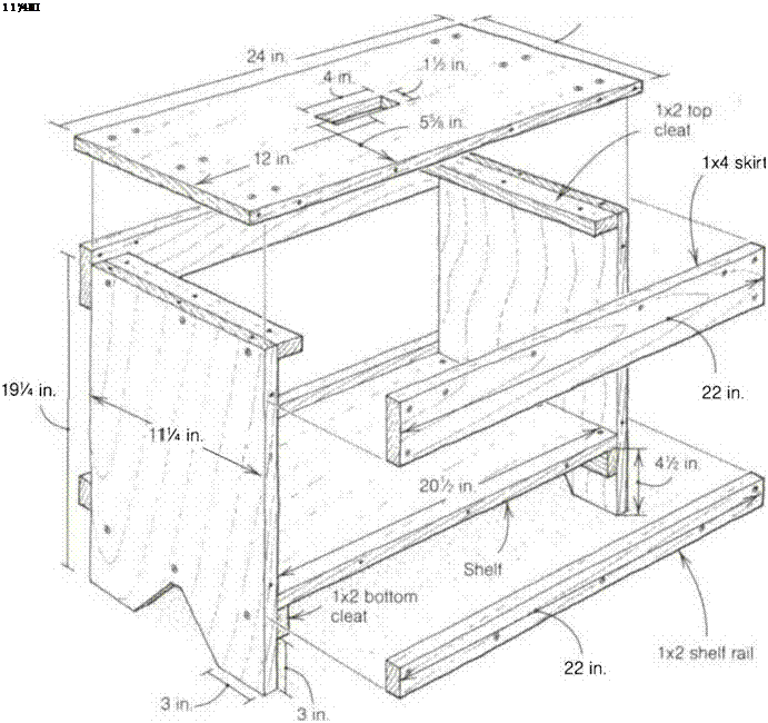
A workbench is a handy item to have on the job site. Here are plans and instructions for building a sturdy 2-ft.-long by 20-in.-high workbench that can be used to carry tools, to support wood that needs cutting, and even to stand on when working overhead.

CUTTING THE PARTS

Begin by cutting the top, the shelf, and the ends.

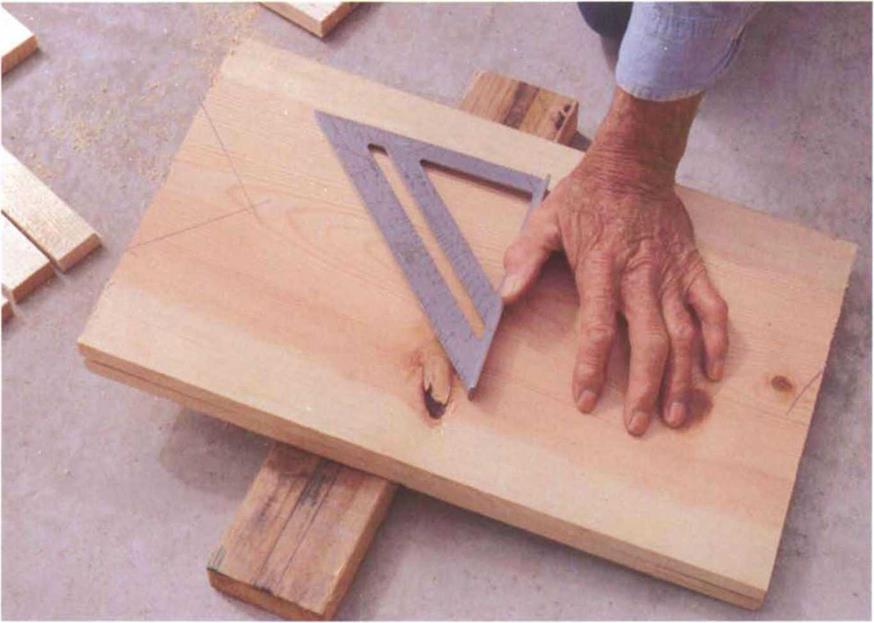
Lay the 8-ft. 1×12 on the floor over a piece of 2x so the cutoff end can fall free, then measure down 24 in. for the bench top. Using a square, mark a line
across the wood at this point. Cut just beside the mark so that the top will be a full 24 in. long. Car­penters sometimes call this “leaving the line.” Don’t worry if the cut isn’t quite perfect.

Now measure 201/2 in. down the 1×12 for the shelf and draw a cut line across it using the square. Make the cut, but remember to leave the line. Lay the shelf and top aside and cut the two end pieces to a length of 191/4 in. from the remaining 1×12.

Tools
Подпись: 1 1 ’/4 ІП Nail apron Hammer Tape measure Pencil

Small square Drill with 3A-in. spade bit, Уіб-іп. twist bit, and Phillips-head bit Reciprocating saw Circular saw

Materials

8-ft 1×12[5]

8-ft. 1×2*

4-ft. 1×4*

About 20, 1 Win.
drywall screws
About 40, 11/2-in.
drywall screws
Ten 6d box nails
80-grit sandpaper

Portable sanders

Portable sanders

To lay out the feet, place one side on top of the other. Measure in 3 in. from each side and use a small square to mark a 45° line to the center.


Lay out the “feet” on the end pieces next. To make the feet identical on both end pieces, place one on top of the other. Measure in 3 in. from the end, hold the small square to this point, and mark a 45° line to the center, creating a V (see the photo above). The top of the V should be about 3 in. from the bottom of each piece. Cut out this V section.

Next, cut two 22-in. skirts from the 4-ft. 1×4. The skirts will help strengthen the bench top. Now grab the 8-ft. 1×2 and cut two 22-in. shelf rails and four 111/4-in. cleats.

ASSEMBLING THE WORKBENCH

Start the assembly by attaching the cleats to the end pieces. The top cleats help tie the ends and top together. The bottom cleats help support and tie the shelf to the end pieces.

Lay one of the end pieces on top of the other, but place them on some 2xs so you don’t drill into the floor. From the top, measure down 3/e in., draw a square line across, and drill three 3/ie-in. holes across the line, spaced evenly. From the bottom, measure up 33A in., draw a square line across, and drill three more holes.

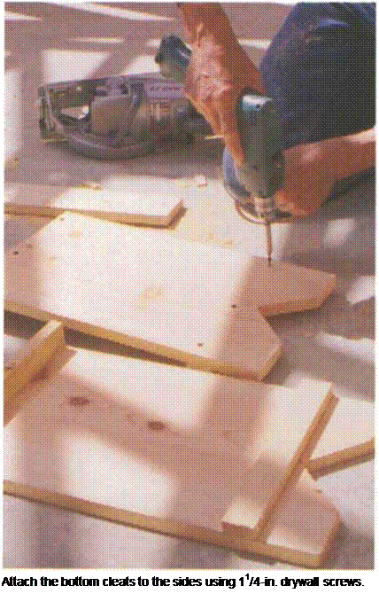
Подпись: Attach the bottom cleats to the sides using 11/4-in. drywall screws.
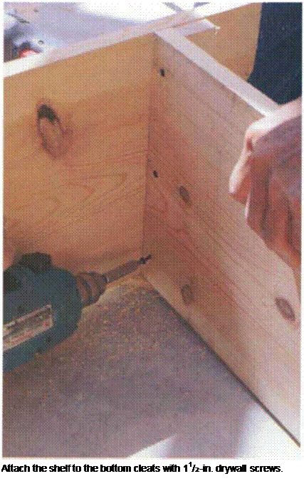
Подпись: Attach the shelf to the bottom cleats with 11/2-in. drywall screws.

Place a cleat on edge on the floor and place an end piece on the cleat flush with the top. Join the two with three 11/2-in. drywall screws. Drive the screws slowly and with care using a Phillips-head screwdriver. If you drive them too fast or too deep, you could strip the screws. If you make a mistake, drill another hole through the side and try again. Repeat for the other side.

Now attach the bottom cleats. To help ensure that the cleats will be level and straight, use a square to draw a line across the side just on top of the V (3 in. from the bottom). The bottom of the cleat should sit flat on that line. Now drive three 11A-in. drywall screws through the holes in the side and into the cleat (see the left photo above). Repeat for the other side.

Portable sanders

Next comes the top, which overhangs the end pieces 1 in. on both sides. On the underside of the top, draw a line 1 in. from each end to mark the outside edge of the end pieces. Hold an end piece to the 1-in. line. Drill three 3/ie-in. holes through the top and drive three 11А-іп. drywall screws or three 6d nails through the top and into each cleat. Repeat for the other side. Now stand the workbench up. Take a look to see if everything is in proportion.

Trust your eye; if it looks good, it is good.

The shelf comes next. Measure in 3/s in. from one end of the shelf, draw a line across with the help of a square, and drill three 3/ie-in. holes along the line, one about 1 in. from each end and one in the center. Repeat on the other end. Set the shelf between the ends and rest it on the bottom cleats. Attach it to the cleats with three 1Уг-іп. drywall screws on each end (see the right photo on the facing page).

Next come the 1×4 skirts. Drill two 3/ie-in. holes 3/e in. from each end of a skirt. Then drill four 3/ie-in. holes along the length about 3/e in. from the edge. Repeat for the other skirt. Attach the skirts flush with the top of the bench using 1 Уг-іп. drywall screws.

Now grab a 1×2 shelf rail and drill one 3/ie-in. hole 3/e in. from each end and three more along the length 3/s in. from the edge. Repeat for the other rail. Attach the bottom of each rail flush to the bottom of the shelf using 1 Уг-іп. drywall screws.
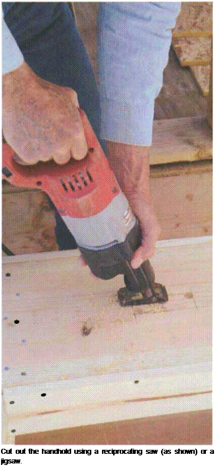
Подпись: Cut out the handhold using a reciprocating saw (as shown) or a jigsaw. It’s nice to have a handhold in the top so that you can move the bench around. In the center of the top, lay out a handhold so that it’s 1 V2 in. wide and 4 in. long. Drill a 3A-in. hole in opposite corners using a spade bit. Use a reciprocating saw or jigsaw to cut out the wood between the holes (see the photo at right). Sand the edges of the hole with 80-grit sand­paper. Then round the corners of the top with sand­paper. Now you’re ready to go to work.