Ships and maritime ports

Initially, the typical vessel in service on the Atlantic coast was the “long boat”, the Viking knorr whose appearance seems to have sown terror in the 9th century, and enabled the Normands to colonize Iceland and Greenland. This is a light boat, easily pulled onto the beach. In the 11th century quite a different type of boat appeared, one of much greater capacity: the cog. The expansion of commerce and the development of more protected harbors led to this evolution in boats. The newer, heavier vessel cannot be hauled up onto the dry beach. Therefore it is not necessary for it to have a flat bot­tom, and consequently its hull evolves toward a round form with a keel. This keel also gives the ship much better nautical performance, since it drifts less in a crosswind. The boat is equipped with an axial rudder. This device was known in China since the 1st cen­tury AD, but it was possibly invented independently on the Atlantic coast of Europe, where the greater freeboard makes it difficult to use the ancient rudder-oar. As was the case for the earlier boats, the cog has a single and very large sail rigged on a yard. The sail area could be increased in light weather by the addition of small sails attached to the edge of the mainsail or reduced in heavy weather using reefing straps sewn into the sail.

These new boats could attain capacities of 200 tons, even 300 tons in the 13th centu-

29

ry. On the Mediterranean Sea, ships having two or three masts and lateen rigging are

used by Italian mercantile cities.

Sheltered embayments progressively become ports with wooden quays, especially starting in the middle of the 13th century. Notable among these are Caen and Rouen in Normandy, developed by William the Conqueror; Genoa, Pisa, Venice, Amalfi,

29 Gies and Gies (1994), pp. 154-158.

Barcelona in the Mediterranean; La Rochelle, Boulogne, Dunkirk, and the cities of Flanders and of northern Germany, linked to the sea by channelized rivers often with outer harbors such as Nieuport for Ypres. In 1169 navigation is made much safer by the widespread adoption of the magnetic compass from China, and by the advent of naviga­tion buoys and markers, and even beacons – fires burning on towers. But for the most part navigation does not continue through the winter months between December and March, as had been the practice since ancient times.

Navigation markers are set on shoals to warn of danger or mark an access channel. Often made of wood, they proliferate around the ports of the English Channel and the North Sea, as well as in the Mediterranean. For example the turret of Meloria was built of cut stone in 1157 in the mouth of the Arno River at the port of Pisa. Lighted beacons had already existed during the time of the Roman Empire, and were not entirely forgot­ten in the Middle Ages. Indeed in 810 Charlemagne had the Tower of Order of Boulogne, originally constructed in 40 AD by the Romans, rebuilt and illuminated.[487] But this development of aids to nighttime navigation accelerates in the 13th and 14th centuries, as shown in table 9.1. However not all of these beacons are permanently illu­minated, for wood is an expensive commodity.

Table 9.1 Lighted beacons between the 12th and 16th centuries (after Fichou, Le Henaff, Mevel, 1999)

Place or Port

Date

Place or Port

Date

Nieuport

1288

Cordouan (entry to the Gironde)

1360

Ostende

1365

Port-Vendres

?

Calais

1290

Aigues-Mortes (tower of Constance)

1246

Dunkirk

1365

Marseille (Ile du Planier)

1319

St. Catherine (Isle of Wight)

1320

La Ciotat

1564

Abbey of point St. Mathieu

1250

Livorno (tower of Meloria)

1158

(extremity of Brittany)

16th

Porto Pi (Majorca)

?

Les Sables-d’Olonne

La Rochelle (tower of the Lantern)

1465

Add smaller shelves to a closet

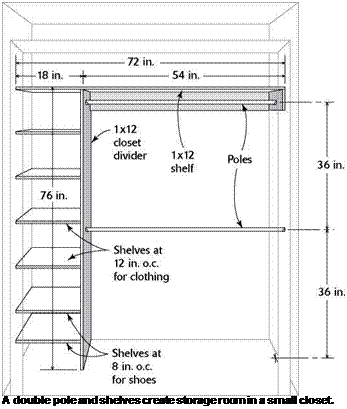
Rather than always running a shelf pole all the way across a closet, you can shorten the pole and add a column of shelves at one end, as shown in the illustration on p. 263. With this design, you can make a typical 6-ft. closet much more useful for storing all kinds of clothes, including shoes. Cut the 1×12 divider 76 in. long, lay out the shelf locations, then attach 1×2 shelf-support cleats to the divider.

I usually place the two lowest shelves 8 in. and 16 in. off the floor for shoes. For socks and underclothes, I place a shelf every 12 in. above the first two. Fasten corresponding cleats to the side of the closet wall where the shelves will be installed.

In a 6-ft.-wide closet, install a vertical di­vider 54 in. from one side or the other. Toenail the divider to the floor. Nail the top shelf (which extends all the way across the closet) to the top of the divider, making sure the divider is plumb.

INSTALLING A BASIC SHELF AND
POLE IN A CLOSET

Подпись: The inside of a closet can be arranged to hold much more than clothes on hangers. A bank of shelves can eliminate the need for a chest of drawers. [Photo by Don Charles Blom]

This allows you to adjust the height of shelves, just as in a kitchen cabinet.

On the pole side of the divider, put a few hooks to hang belts. On the cleat holding the shelf on the other end, install a hook or two to hold clothes you don’t want to put on a hanger. Now you have a much more usable closet with little added expense or labor.

Trim out a closet with coated-wire shelving

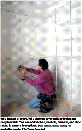
The rubberized wire shelving found at home centers offers many accessories to help organize a clothes closet. The wire frames are strong and open, and you don’t have to paint them (see the photo on p. 265). Besides the traditional shelf – and-pole setup, you can install baskets, drawers, and tie, belt, and shoe racks. The possibilities for arranging your closets with these components are really endless. The only drawback is that they’re more expensive than building simple storage spaces with wood.

I haven’t installed a lot of this type of shelv­ing, but it isn’t difficult. The instructions that come with the components are easy to follow. Just be sure to make accurate measurements so the shelving is installed straight and level. Some people put backing in the wall frame be­fore drywall is installed so the hooks that hold

Add smaller shelves to a closetAdd smaller shelves to a closet

Bringing pipes and electrical wire through the back of a Cutting exact angles is easy when you have a chopsaw.

base cabinet calls for careful measurements. A tight-fitting miter really looks nice.

We tackle the baseboard trim after all the cabinets have been installed.

Add smaller shelves to a closetПодпись: COLORFUL CHARACTER FOR A HOME We once rehabbed a house for a couple with seven children. The father, Eddie, had never had his own bed as a child. As we worked together fixing up the house that would become his family's new home, it was clear that he was overwhelmed with pride. Eddie had a colorful personality, and he loved color in every aspect of his life. Each room in his soon-to-be completed house was to be painted a happy color—hot pink for his girls, electric blue for his boys. And on the outside? Bright-yellow vinyl siding. After the house was finished, Eddie and his family came to our church to thank the congregation for sponsoring the rehab of their new home. Striding down the aisle with his wife, Shandra, and all their kids, Eddie—who's at least 6 ft. 3 in. and rail-thin—was all smiles. What a happy man he was that day. But he wasn't the only one smiling. As Eddie and his family made their way to the front of the church, past the 900 people sitting in their pews, I couldn't help noticing his shoes, and I smiled myself. They were fire-engine red. Color, obviously, is important to Eddie. —Anna G. Carter Add smaller shelves to a closet

the wire units can be screwed into solid wood. Otherwise, you can screw the hooks into studs and use the drywall anchors that come with the shelving units in places where you need support but don’t have a stud.

Install shelves in linen closets and the laundry room

A complaint I hear from many homeowners is that they just don’t have enough places to store their belongings. Certainly, most of us could stand to reduce the clutter in our lives, but ad­equate storage space is in short supply in small, affordable houses. For that reason, it makes sense to get the most out of whatever storage space you do have.

Just as in a clothes closet, you can do a lot with a linen closet by building shelving like that shown in the illustration on p. 263. I like to in­stall the first shelf at 18 in. to 20 in. off the floor, then place shelves every 12 in. to 16 in. up from there. Use 1 x2 cleats on each side of the closet, and attach the shelving to the cleats.

Take advantage of all the space in a linen closet (usually around 24 in.) by using full-depth shelves. Melamine shelving is available in vari­ous standard widths up to 24 in., or you can buy 4-ft. by 8-ft. sheets of the material and cut it to the desired width.

Laundry rooms are often just large enough to hold a washer and dryer. Few affordable houses have a large utility room with space for lots of shelves. In a small laundry room, I install a couple of shelves over the washer and dryer for items such as soap and bleach.

I install the first shelf at 5 ft. off the floor and another one above the first. Or you can buy a simple wall cabinet and attach it to the wall.

Another strategy to consider is using built-ins to gain space. Most home centers sell an ironing board in a cabinet that fits neatly between two wall studs. You may want to build a bookcase that fits into the wall. I often like to build a small box with a shelf to place in walls here and there. This provides a place for a vase with flowers or other knickknacks.

Add smaller shelves to a closet

EVALUATION OF CONFORMITY

Asphalt mixtures are construction products and the standards EN 13108-1 to 13108-7 are harmonized with the Construction Products Directive 89/106/EEC. The system “2+” has been adopted to evaluate conformity of asphalt mixtures. It consists of the following:

• Initial type testing of each mix produced by its manufacturer

• Certification of a Factory Production Control (FPC) with reference to EN 13108-21 conducted by a notified body, separate for each production site (asphalt plant)

The SMA design process (recipe) should be followed by confirmation that the mixture meets all requirements shown in the relevant categories listed in the NAD; if it does meet the requirements, it cannot enter the market. This set of tests, called initial type testing, is based on requirements of the standard EN 13108-20 (Table B.5), which include the following:

• Binder content EN 12697-1 and 12697-39

• Grading EN 12697-2

• Void content including VFB EN 12697-8

• Void content of gyratory compacted samples EN 12697-31

• Binder drainage EN 12697-18

• Water sensitivity EN 12697-12

• Resistance to abrasion by studded tires EN 12697-16

• Resistance to permanent deformation EN 12697-22

• Resistance to fuel (airfields) EN 12697-43

• Resistance to deicing fluids (airfields) EN 12697-41

Routine (daily) testing of a manufactured mix is conducted using a system of FPC according to the standard EN 13108-21.

From Locks to Smoke Detectors

IT WAS THE GREAT YANKEE CATCHER, Yogi Berra, who said of baseball, “It ain’t over ’til it’s over.” The same is true of building a house. Even as you finish the interior painting, install the cabinets, and complete all the plumbing and electrical work, there’s still plenty to do before a new house is ready to welcome its first inhabitants. Although most of these final tasks are small compared to the major construction stages that have already been done, there are a surprising number that belong on what some contractors refer to as punchlist. Such tasks range from installing the toilet-paper holder and mounting a fire extinguisher to nailing up house numbers and putting in the medicine cabinet. Taken together, these little assignments can demand just as much of your time—and possibly more—than some of the bigger jobs you did ear­lier. The step-by-step format in this chapter will help you divide these details into manageable chunks of work.

STEP 1 Install the Hardware and Fixtures

Most finish hardware will be seen and used for the life of the house, so take your time installing items such as door locks, drawer pulls, and towel bars. Once they’re

Подпись: STEP BY STEP

1 Install the Hardware and Fixtures


3 Get to Know Electrical and Mechanical Systems

4 Prepare for the Worst


2 Select and Install the Finish Flooring


/.-■S’). • ■

s-i-4-

•і

v’ ;

Ш ‘ ‘-‘«к %*>*

• v& – ’ 1 •* 1 j

– • ;

1 •/::■• «./лі j

ШЬЖ

J/7% ‘•:••’

[…………. – ~

■ * ‘” " Wj^/v ^ .. -«.v — ;:■•■”■ *• ■•■ **v;.’ – У-У–

…………………. 1


From Locks to Smoke Detectors

Подпись: Helping HandПодпись: Buy your welcome mat early! To reduce the amount of dirt that gets tracked into a house after new carpeting and vinyl and wood flooring have been installed, set up some sort of dirt-catching mat. Put it by the front door near a sign that says '"Please wipe your feet or remove your shoes."

installed neatly and accurately, they’ll look attractive and work well for a long time. Keep in mind that safety items, such as grab bars, also need to be installed securely so that they’ll be safe to use.

Development Phase

Objective. In the development phase, the alternatives that have survived the selection process are developed into firm, specific recommendations for change. The process involves not only detailed technical and economic testing but also an assessment of the probability of successful implementation.

Key Questions. Several questions must be answered about each alternative during the development of specific solutions:

Will it work?

Will it meet all necessary requirements?

Who has to approve it?

What are the implementation problems?

What are the costs?

What are the savings?

Procedures

1. General. To satisfy the questions above, each alternative must be subjected to:

a. Careful analysis to ensure that the user’s needs are satisfied

b. A determination of technical adequacy

c. The development of estimates of costs and implementation expenses, including schedules and costs of all necessary tests

d. Consideration of changeover requirements and their impact

2. Develop convincing facts. As in the information phase, the use of good human relations is of considerable importance to the success of the development phase. In developing answers to the questions above, the VE team should consult with personnel knowledgeable about what the item must do, within what constraints it must perform, how dependable the item must be, and under what environmental conditions it must operate. Technical problems related to design, implementation, procurement, or

operation must be determined and resolved. Consideration must also be given to impact in areas such as safety, fire protection, maintenance, and supply support.

3. Develop specific alternatives. Those alternatives that stand up under close tech­nical scrutiny should be followed through to the development of specific designs and recommendations. Work on specifics rather than generalities. Prepare drawings or sketches of alternative solutions to facilitate the identification of problem areas remaining in the design, and to facilitate detailed cost analysis. Perform a detailed cost analysis for proposed alternatives to be included in the final proposal.

4. Development implementation plans. Anticipate problems relating to implementa­tion, and propose specific solutions to each. Particularly helpful in solving such problems are conferences with specialists. Develop a specific recommended course of action for each proposal that details the steps required to implement the idea, who is to do it, and the time required. Ask for ideas from the office that will approve or disapprove the recommendation.

5. Testing. When testing is involved, the VE team may arrange the necessary testing and evaluation, although normally this will be done by other appropriate personnel in the organization. This testing and evaluation should be planned for and scheduled in the recommended implementation process.

6. Select first choice. Finally, one alternative should be selected for implementation as the best-value (best overall cost reduction, usually) alternative, and one or more other recommendations selected for presentation in the event the first choice is rejected by the approval authority. The implementation schedule that will yield the greatest cost reduction should also be indicated.

Design of Drainage Systems

The construction of new roads can cause impacts on the water resources of affected regions, causing irreversible effects in some cases.

Surface and subterranean water resources are finite and irreplaceable natural re­sources for survival, therefore their protection against abnormal flow and against pollution is of great importance, nowadays making their preservation an indispens­able part of a sustainable development policy. For this reason it is fundamental that a drainage system be developed that regulates the flow of effluents from the pavement platform, that controls the subterranean drainage and that minimises the hydrological impacts of the road on the environment.

An example of pavement sealing was seen in Slovenia for highways crossing very highly sensitive aquifers. There, the following requirements are used (Ajdic et al. 1999).

Fig. 13.38 An asphalt overlay over a concrete pavement showing severe reflection cracking. Re­produced by permission of MacPave Corporation

• In the asphalt layer the permeability can be controlled via the air void ratio (see Chapter 5). The wearing course of the asphalt layer should include not more than 5% air voids and the base course not more than 7% air voids.

• A stress absorption membrane should be constructed using a polymer modified bitumen in a layer of 1.5-2.0kg/m2 and appropriate fine aggregate. Junction sealing should be performed with bituminous tape.

An example of the use of a lining system beneath an embankment is Highway A-15 at Botlek in part of Europoort, Rotterdam (in the Netherlands). Approxi­mately 400 000 t of (municipal solid waste) incinerator bottom ash was used in an embankment for this major roadway construction. The ash was covered with a compacted sand-bentonite mixture with a minimum thickness of 20 cm to reduce water infiltration. The formation (founding level) of the embankment was shaped so as to bring any water seeping through the ash to a sampling point at which quan­tity and quality of seeping water could be monitored. The aim of the cover and lining systems was to prevent the contamination of underlying clean groundwater by infiltrating water that would have passed through the ash embankment material, potentially collecting undesirable contaminants on the way. In fact, due to the heavy industrial use of the land in Europoort over many years prior to the embankment’s construction, the natural groundwater is degraded at a regional scale, so use of the ash posed few risks of causing unacceptable contamination (Mank et al. 1992).

At another site in the Netherlands, a wind barrier was built at Caland (Stoelhorst, 1991). This project, built in 1985, used more than 650 0001 of bottom ash in an em­bankment 700 m long and 15 m high. The ashes were covered with a primary cover of 0.5 m of compacted clay with a sand drainage layer (0.5 m thick) and top soil (1m thick) overlaying the clay layer. The slope of the compacted ash was between 40% and 50%. As at the Botlek site, groundwater quality is monitored, in this case on both sides of the embankment.

Dishwashers: Less Hot Water Equals Less Energy Use

WHAT TO LOOK FOR

• The Energy Star label. Energy Star- qualified dishwashers are at least 41% more energy efficient than the federal minimum. Keep in mind that some mod­els exceed the standard significantly more than others; check the EnergyGuide label or the list of qualifying dishwashers at www. energystar. gov for high-performing machines.

• Soil sensing. With this technology, "fuzzy logic" is used to determine how dirty the dishes are. Water use and wash cycle are adjusted accordingly, saving significant water and energy.

• No-heat drying. Most dishwashers have an electric heating element and fan for drying dishes. Make sure the one you buy has a no-heat drying option, which can save a significant amount of energy.

usage tips

• Insulate hot-water pipes from the water heater so that water stays hot all the way to the dishwasher and doesn’t cool off as much between the different wash and rinse cycles.

• Wash full loads only, even if it means waiting a day or two.

• Avoid high-temperature cycles. Many dishwashers have a setting for more inten­sive cleaning in which the temperature is boosted, which can significantly increase electricity use per cycle. To conserve energy, don’t use this setting.

Подпись:

Dishwashers: Less Hot Water Equals Less Energy Use Dishwashers: Less Hot Water Equals Less Energy Use

Alex Wilson is founder and executive editor of Environmental Building News and president of BuildingGreen Inc. in Brattleboro, Vt. (wwwbuildinggreen. com). His latest book is Your Green Home (New Society Publishers, 2006).

Dishwashers: Less Hot Water Equals Less Energy Use

Подпись: ю

Evaluation Phase

Objectives. The purpose of this phase is to select the most promising alternatives from among those generated during the previous phase. During the creativity phase there is a conscious effort to prohibit any judicial thinking so as not to inhibit the cre­ative process. But in the evaluation phase, all the alternatives must be critically evalu­ated because many of them may not be feasible. The alternatives are studied individu­ally and/or grouped for the best solution. Identifying function may seem like a simple process—so simple, in fact, that it seems only a “simple” mind would be required to get the job done. In some ways this is true; a mind that can work in a simple, direct way is required—a mind with the ability to reduce concepts, ideas, and analyses to their best common denominators. The emphasis on function in this phase is what makes the VE approach radically different from any other cost reduction effort.

Key Questions. The following questions must be answered about all alternatives being developed during this phase:

What does each alternative cost?

Will each perform the basic functions?

Techniques. Several techniques are available by which alternative ideas can be evaluated and judged. Comparisons can be made between the various advantageous and disadvantageous features of the alternatives under consideration. Advantages and dis­advantages of each alternative can be listed and then the ideas sorted according to the relative numbers of advantages and disadvantages. A system of alternately using creative

TABLE 10.2 Questions to Stimulate Ideas

A. Idea stimulators

Eliminate—combine:

Can it be eliminated entirely?

Can part of it be eliminated?

Can two parts be combined into one?

Is there duplication?

Can the number of different lengths, colors, types be reduced?

Standardize—simplify:

Could a standard part be used?

Would a modified standard part work?

Does the standard contribute to cost?

Does anything prevent it from being standardized?

Is it too complex?

Can connections be simplified?

Challenge—identify:

Does it do more than is required?

Does it cost more than it is worth?

Is someone else buying it at lower cost?

What is special about it?

Is it justified?

Can tolerances be relaxed?

Have drawings and specifications been coordinated? Maintain—operate:

Is it accessible?

Are service calls excessive?

Would you like to own it and pay for its maintenance?

Is labor inordinate to the cost of materials?

How often is it actually used?

Does it cause problems?

Have users established procedures to get around it? Requirements—cost:

Are any requirements excessive?

Can less expensive materials be used?

Is it proprietary?

Are factors of safety too high?

Are calculations always rounded off on the high side?

Would a thinner material work?

Could a different finish be used?

B. Analysis techniques

Review all phases of the program being evaluated (speculation phase).

Designate the subordinate problems requiring solution (analysis phase). Determine the data that might help with the evaluation (speculation phase). Determine the most likely sources of data (analysis phase).

Conceive as many ideas as possible that relate to the problem (speculation phase). Select for further study ideas most likely to lead to a solution (analysis phase). Consider all possible ways to test the ideas chosen (speculation phase).

Select the soundest ways of testing the ideas (analysis phase).

Decide on the final idea to be used in the program (analysis phase).

(Continued)

TABLE 10.2 Questions to Stimulate Ideas (Continued)

C. Analysis criteria

Will the idea work?

Can it be modified or combined with another?

What is the savings potential?

What are the chances for implementation?

What might be affected?

Who might be affected?

Will it be relatively difficult or easy to make the change? Will it satisfy all the user’s needs?

and judicial thinking processes for each basic idea to be evaluated can be applied according to the steps shown in the Analysis Techniques portion of Table 10.2.

Procedure. Evaluation may be accomplished either by the generating group or by an independent group. Authorities disagree upon which approach is better. The disagree­ment grows out of the question of whether people who generate ideas can be objective enough in evaluating them.

1. Establish criteria. The first step is to develop a set of evaluation criteria or standards by which to judge the ideas. In developing these criteria, the team should try to anticipate all effects, repercussions, and consequences that might occur in trying to accomplish a solution. The resultant criteria should, in a sense, be a measure of sensi­tivity to problems (which might be inherent in changes caused by the new idea). In Table 10.3, three sets of criteria that could be used in the analysis phase are presented under Possible ratings. Factors such as these are really the yardsticks by which the effectiveness of each idea can be tested.

2. Screen ideas. The next step in the procedure is the actual ranking, or rating, of ideas according to the criteria developed. No idea should be summarily discarded; all should be given this preliminary evaluation as objectively as possible. In Table 10.3, a three-part system that can be used to rate ideas is presented under Alternative idea. Ratings and their weights are based on the judgment of persons performing the evalua­tion. This initial analysis will produce a shorter list of alternatives, each of which has passed the evaluation standards set by the team.

TABLE 10.3 Typical Analysis Rating System

Possible ratings

Excellent

Good

Fair

Poor

Use now

Modify

Hold

Reject

Simple idea

Moderately complex

Complex idea

3. Define alternatives. The remaining alternatives can be ranked according to an estimate of their relative cost reduction potential. The ranking may be based on nothing more than relative estimates comparing the elements, materials, and processes of the alternatives and the original or present method of providing the function. The surviving alternatives are then developed further to obtain more detailed cost estimates. The cost estimating for each alternative proceeds only if the preceding step indicates it still to be a good candidate. Although the analysis phase is the responsibility of the VE team, authorities and specialists should be consulted in estimating the potential of these alternatives. Cost estimates must be as complete, accurate, and consistent as practicable to minimize the possibility of error in assessing the relative economic potential of the alternatives. Specifically, the method used to determine the cost of the original should also be used to cost the alternatives.

4. Make final selection. After the detailed cost estimates are developed for the remaining alternatives, one or more are selected for further study, refinement, testing, and information gathering. Normally, the alternative with the greatest savings poten­tial will be selected. However, if several alternatives are not decisively different at this point, all should be developed further.

FITTING BASEBOARD IN IMPERFECT CORNERS

PREVENTING BASEBOARD FROM TOEING IN


The joints in baseboard should be close to per­fect. Minor touchups with latex caulk can be done before painting. Unfortunately, it’s not so easy to make perfect joints at corners when the drywall is not straight or a corner is not square.

On inside corners, drywall can be tipped back, causing a coped or mitered baseboard joint to open. This can be remedied by putting a shim be­hind the tipped trim so that it sets straight up and down. Instead of a shim, I sometimes drive a dry – wall screw into the bottom plate to hold the base­board square (see the illustration at right).

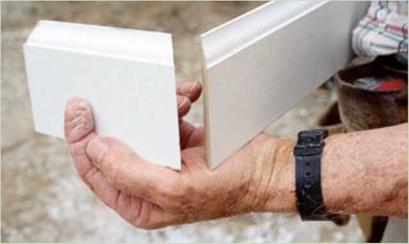
I use two short pieces of baseboard with mi­tered (45-degree) ends to check outside corners for square (see the photo right). If the mitered joints fit perfectly, the corner is square. If not, note whether the joint is open at the heel (the back corner of the baseboard) or at the toe (the front edge). If it’s open at the heel, set the chopsaw at a 44-degree angle (or less, if necessary) before making the cut. If it’s open at the toe, set the saw at a 46-degree angle (or more, if appropriate). Rather than waste long pieces of material, make practice cuts on scrap until you get the right fit.


Drywall


Screw


Baseboard


Drywall, especially in the corners, can taper inward, causing the baseboard to pull away from the wall at the top.


To prevent this, drive a drywall screw into the bottom plate behind the baseboard to hold the baseboard plumb.


FITTING BASEBOARD IN IMPERFECT CORNERSFITTING BASEBOARD IN IMPERFECT CORNERSFITTING BASEBOARD IN IMPERFECT CORNERS

FITTING BASEBOARD IN IMPERFECT CORNERS

Подпись: Offset closet doors make sense. Instead of framing a closet doorway in the center of the closet space, consider offsetting the doorway to one side. This will leave space at one end of the closet to make cubby-holes for folded clothing and shoes.

the other to help hold the miter firmly together. Predrill the nail hole so you don’t split the wood.

To cover a long wall, join two pieces of baseboard with a 45-degree scarf joint. It’s best to break the joint over a stud. Cut the first piece of trim, and install it with the long point of the miter at the back of the material. The second piece is cut with the long point of the miter at the front of the material. The second miter laps over the first to make a tight joint.

The last piece of baseboard in a room should have a coped joint on one end. The
other end will have a square cut that butts into the door casing.

FINISH UP. Pieces of baseboard will be at slightly different elevations where carpeting meets vinyl flooring. Join the two pieces of baseboard with a square cut, and use sandpaper to round the corner of the higher piece so that it meets the lower one (see the illustration on p. 261).

Other situations require a bit of finesse. For example, you can’t run baseboard in front of a heat register that goes all the way to the floor.

In that situation, bevel each end cut 15 degrees
instead of making a right-angled cut (see the illustration on p. 261).

Cabinet manufacturers sometimes supply a prefinished baseboard that matches their cabinets. This base material is cut and nailed under the front of the cabinets in the toekick space. Once installed, it hides the joints between the cabinets.

If that cabinet trim is not available, you can cover the toekick area with a regular piece of baseboard trim. You may also want to install base shoe, or shoe trim, a small, quarter-round type of molding that is often used with base­board trim (see the illustration on p. 261). Shoe trim hides any space that may exist between the baseboard and hardwood or vinyl flooring. Because it’s so small, it’s quite flexible (much more so than baseboard), so it can be bent to fit the contour of a wavy wall or floor. It is not needed with carpeting because carpeting fills the space between the baseboard and the floor.

If you’ve hand-nailed all the interior trim, you now need to drive all the finish nails below the surface of the wood with a nail set. Once set, the holes can be filled with putty and sanded in preparation for painting. Caulk along the top edge of the baseboard trim and along the casings to fill any gap between the trim and the wall. Remember that caulk shrinks, so some gaps may need a second application. Take your time when caulking baseboard. Leave joints looking neat, not messy.

Chair rail adds character

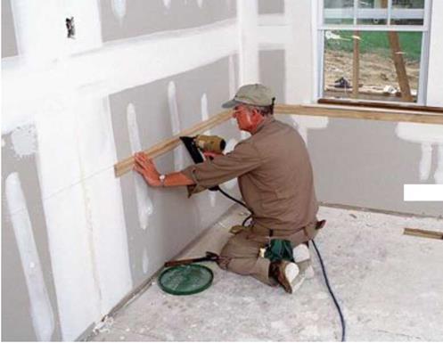
Подпись:FITTING BASEBOARD IN IMPERFECT CORNERSПодпись: MAKING A CLOSET INTO A MORE USABLE SPACEПодпись:Chair rail is another type of traditional trim that is installed horizontally and often used in kitchens, dining rooms, and sometimes hallways. In days past, chair rail protected the wall from being marred by the backs of chairs. Today, it is mainly used to add character to a room. Chair rail is cut and installed just like baseboard (see the photo above). Join two pieces with a coped joint at inside corners and a mi­tered joint at outside corners. Nail the chair rail directly to the wall studs, with the top of the rail 36 in. from the floor.

STEP 7 TRIM OUT THE CLOSETS

Most closets in affordable houses get nothing more than a shelf and a pole. It’s my opinion that we can do much better without a lot of effort or expense. Very little extra material is needed to add shelves for socks and underwear, to make a place to hang belts and ties, and to make cubbyholes for shoes. Experience tells me that people like and use such storage. Even if you don’t want to build special storage bins, you can buy them. Many people now use the wire shelv­ing available at home centers.

Install shelves and poles

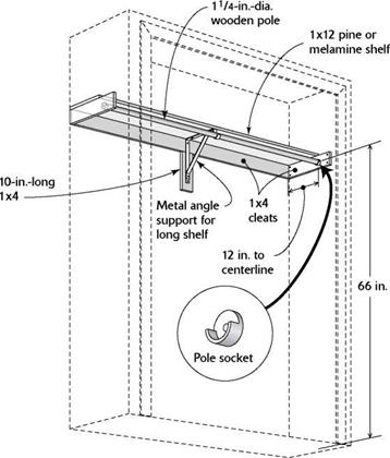
To install a basic shelf and a pole in a closet, measure 66 in. from the floor and mark the back and sides of the closet (see the illustration on the facing page). Then cut cleats (also called rails or ledgers) from 1×4 stock and nail each cleat so its top edge is on a line. Drive two 8d finish nails through the 1x rails and into each stud.

Cut the shelves from 1×12 pine or melamine (particleboard covered with white plastic lami­nate). A standard closet shelf extends from wall to wall. I like to secure the shelf with a couple of nails driven into the cleat. It’s a good idea to predrill the nail holes.

In a small closet, where the shelf and pole are just 3 ft. long or so, no mid-span support for the shelf or pole is necessary. Each end of the pole rests in a socket that is screwed to a side cleat.

In a larger closet, both the shelf and the pole need additional support from metal brackets. Place a bracket against a side cleat to determine the location of the pole sockets. This ensures that the sockets and brackets will support the pole at the same level. Attach the top part of the bracket to the 1×4 horizontal cleat on the back wall, then nail a 10-in.-long piece of 1×4 perpendicular to the cleat and over a stud to support the bottom of the bracket (see the il­lustration on the facing page).

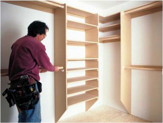
Shelves customize a closet. Attaching shelves to a closet wall creates more storage space while giving you more flexibility in locating the closet pole.

FITTING BASEBOARD IN IMPERFECT CORNERS[Photo by Roe A. Osborn, cour­tesy Fine Homebuilding magazine © The Taunton Press, Inc.]
Remember that cleats along the back and end edges should also support the top shelf, as discussed previously.

Подпись:Cut the shelves to fit between the divider and the closet wall, then nail them to the cleats to further secure the divider.
On what will be the clothes-hanging side of the closet, attach a 1×4 cleat to the divider at 66 in. to support the pole. Or you can install two poles, one at 72 in. and one at 36 in. The pole sockets are attached to the cleats and the divider.

If you’d prefer to buy shelving rather than make it, you can find plastic-coated 1x12s with shelving holes already drilled in them at most home centers. The shelves sit on small shelf pins that fit into the holes drilled into the divider.

iiiiiiiiiiiiiiiiiiiiiiiiiiiiiiiiiiiiiiiiiiiiiiiiiiiiiiiiiiiiiiiiiiiiiiiiiiiiiiiiiiiiiiiiiiiiiiiiiiiiiiiiiiiiiiiiiiiiiiiiiiiiiiiiiiiiiiiiiiiiiiiiiiiiiiiiiiiiiiiiiiiii

FITTING BASEBOARD IN IMPERFECT CORNERS

APPLYING A WATER-BASED FLOOR FINISH

Applying a water-based polyurethane does not differ much from applying an oil-based finish and, as noted in the preceding section, water – based finishes are more benign. Although "Finishes, Cleaning Solvents, and Applicators,” on p. 494, offers general guidance, consider the can label as the last word on drying times, recommended applicators, and so on.

Cutting the edge is the first step when apply­ing any type of floor finish. Use a brush or paint pad to apply a 6-in. swath of finish around the perimeter of the room, along cabinet bases—in short, any place that would be difficult to edge with a large applicator. Pour finish into a sloping paint tray with a replaceable liner, so you can easily reload the paint pad, brush, or large applicator.

If you’re applying a slow-drying finish, you can edge the whole room before switching to a large applicator. However, because water-based finishes dry quickly, it’s best to edge one section

Подпись:Подпись: Subflooring is usually CDX plywood or OSB (oriented strand board) panels whose long edges run perpendicular to the joists—although in older houses, subflooring may be 1-in. boards run diagonally. For joists spaced 16 in. on center, 3/4-in.-thick panels give floor fasteners plenty to grip; 5/i in. is minimal. To allow for expansion and to minimize squeaks, leave Vin. gaps between square-edged panels, nailing the panels to joists every 6 in.; ring-shank or spiral nails hold best. (T&G panels have integral expansion gaps, so butt their edges tight.) Undersize subflooring often sags between joists, creating high spots over the joists and floors that are springy and squeaky. Adding blocking between the joists may stiffen and quiet floors. Underlayment is a layer—over the subflooring—to level out and add rigidity to the subflooring and the finish flooring that follows. Underlayment is especially important if the flooring image1007Подпись: JoistПодпись: Plywood subfloorimage1008Подпись: Finish floor Underlayment

of a wall at a time, so you can use a T-bar appli­cator to overlap edged borders while they’re still wet. Maintaining a wet edge is the key when applying water-based finishes: Edges that dry before they’re overlapped have a distinct lap mark.

Working the floor with a T-bar applicator is like a ballet with chemicals. After cutting the edge, pour a thin puddle of finish along one wall, paral­lel to the floorboards, but stop the puddle 3 ft. to 4 ft. shy of the far wall. Holding the applicator pad at a slight angle—somewhat like a snowplow blade—pull the applicator through the finish. Angle the applicator so that excess finish flows toward the inside of the room so you can spread it out on the return pass. The ballet comes at the end of each turn, as you sweep the applicator pad 180°, spread the finish evenly, and set up for the next pass. It’s easier to do than to describe.

Periodically pour more finish in a long puddle to maintain a wet edge. Having a second person to pour the finish and touch up missed spots is helpful but not essential. If you see a missed spot after the finish has started to set, let it dry and be sure to coat that area the following day, when you apply the next coat. Once each coat is dry, screen – sand it lightly, vacuum, and dry-mop it with a tack rag over the mop. Then apply the next coat.

image1009

Square-edge wood strip flooring is face-nailed, so use a straightedge to line up the nails for a neat, professional appearance. Because tongue – and-groove flooring is nailed through the tongues, those nails are hidden.

In general, don’t walk on the floor till the final coat has cured at least 3 days, and—because this finish is water based—do not damp-mop it for a month.