How Much Hot Water Do You Need?

Most Americans use about 20 gal. of hot water a day, a standard industry benchmark. Most hot-water tanks are sized for a single day’s consumption, so an average family of four, for example, might end up with an 80-gal. tank. Solar hot-water systems should
have no trouble delivering that kind of volume, but there aren’t any safe generaliza­tions about whether it will be enough to satisfy household demands.

"The thing with hot water is that there are wide variations in demand," says Brad Collins, executive director of the American Solar Energy Society. "A 3,000-sq.-ft. house occupied by two elderly people will have substantially less demand than the exact same house next door that has five people, including two teenage girls. Their demand is tenfold what it is in the other house."

Other variables include the time of day when demand for hot water is high-

I Passive Thermosiphons Rely on Convection

Heated water to storage tank


How Much Hot Water Do You Need?

Hot

water to fixtu res 3d


Cold water in


Hot-water storage tank/water heater


How Much Hot Water Do You Need?How Much Hot Water Do You Need?How Much Hot Water Do You Need?

est, whether use comes all at once (morn­ing showers, for example) or is distributed throughout the day, the number of appli­ances in the house and when they are used, and the amount of solar potential the house has. "It’s a different environment for each and every house," says Collins. "It’s very much occupant-driven."

If there’s such a thing as an average, the Arizona Solar Center estimates that a solar hot-water system should be able to deliver 100% of hot water in the summer and about 40% on a year-round basis. Performance var­ies by region. A household of four people would need 40 sq. ft. of collectors for an 80-gal. tank in Arizona, 55 sq. ft. in South Carolina, and 106 sq. ft. in Vermont.

How this translates into savings on gas or electric bills is also a wild card. Most solar hot-water systems are used to heat water before it goes into a conventional water heater, not as an outright replacement for a water heater fueled by gas or electricity. Careful consumers who are flexible about when they use hot water will see more solar benefit than a family that wants a lot of hot water all at once. Under the right circum­stances, virtually all of a household’s hot – water needs can be met by a solar system.

But that’s no guarantee.

"It’s like buying a Toyota® Prius®," says Collins, likening an investment in solar hot water to owning one of Toyota’s hybrid cars. "You change the way you drive because it’s rewarding. You see how your involve­ment can impact your miles per gallon. In the same way, your involvement can im­pact how much energy you’re going to be charged for, whether it’s thermal or electrical energy. People become energy literate and smart energy consumers."

Wood Flooring over Concrete

Before purchasing wood flooring for installation over concrete slabs or in sub­grade areas, check the flooring warranty to see if subgrade installations are allowed. If so, be sure to correct excess moisture conditions beforehand. In general, engi­neered wood is a better choice than solid-wood flooring in such locations because engineered wood’s cross-ply construction is more dimensionally stable. And thanks to impregnated acrylics and other factory finishes, it’s also more water resistant.

Solid-wood flooring is typically installed by first covering the concrete slab with a 6-mil polyethylene vapor barrier, spacing 2×4 sleepers on-face every 12 in. to 16 in. over the plastic, and then using power-actuated fasteners to attach the sleepers to the slab. Although it’s possible to nail 3/4-in. T&G flooring directly to sleepers, it is likely to deflect. Most flooring manufacturers specify a 3/4-in. plywood subfloor, with panels run perpendicular to the 2x4s, a %-in. gap between panel edges, and a V2-in. expansion space around the perimeter of the subfloor.

Engineered wood and plastic-laminated flooring can be nailed or stapled to wood subflooring, glued directly to a slab, or "floated" over it. Floating systems typically call for the planks to be glued or attached to each other, rather than to the subfloor or slab. Many systems feature proprietary underlayments that block moisture and cold and cushion the flooring so you feel less like you’re walking on concrete. Cosella-Dorken’s DELTA®-FL underlayment is a dimpled plastic membrane, and other systems employ foam or felt pads. Floating systems can be used over slabs with radiant heating, as well.

Подпись: Creating a Paper TemplateПодпись: 1-in. gap not covered by paper Alignment notch Подпись: Perimeter of roomimage1018Подпись: Cutout for toilet flangeПодпись: By scribing the perimeter of a room onto felt building paper, you create a full-size template that you can transfer to the resilient flooring. Taping over boat-shaped cutouts keeps the template from moving.Подпись:

Resilient Flooring

Resilient flooring surfaces, such as vinyl and linoleum, bounce back from use and abuse that would gouge or crush harder, less flexible materials. However, vinyl and linoleum are rela­tively thin, so their durability depends on a sufloor that’s thick enough and an underlayment layer that’s smooth, stiff, and flat.

Resilient flooring is installed either as tiles or as sheets; both require underlayment. Tiles are generally easier to install—their layout is similar to that for ceramic floor tiles, as described in Chapter 16, but are poorly suited to high-moisture areas because of their many seams. Resilient sheets are better for kitchens and bathrooms, as suggested in the kitchen installation shown here.

Overlap paper seams at least 2 in. and tape together.

"Boats" cut out and covered with duct tape

15-lb.

building paper

<-

Alignment

notch

image1019

LOW-MAINTENANCE

CHOOSING AN UNDERLAYMENT

Because resilient materials are thin—between /б in. and ъАб in. thick—they will telegraph sub­surface irregularities, such as board joints, holes, and flooring patterns. So underlayment materials must be uniformly flat (no holes or voids), smooth, stiff, and dimensionally stable. Few materials fit the bill. Note: It’s possible to adhere resilient flooring directly to concrete slabs, old resilient flooring, and wood flooring, but that often requires a lot of prep work to make such surfaces perfectly smooth. So in addition to creating a more durable, smoother resilient floor, underlayment speeds up its installation.

Plywood. Plywood is universally acceptable if it’s correctly installed and is exterior-grade APA – rated CDX underlayment. It will be stamped “underlayment” or "plugged crossbands.” Also, it should be at least ‘/a in. thick and have a fully sanded face (FSF)—not plugged and touch sanded (PTS). Type 1 lauan plywood, which has an exte­rior glue, is also specified by many resilient floor­ing makers; panels should be at least 14 in. thick. Three face-grades of lauan are acceptable as underlayment: BB, CC, and OVL. Type 2 lauan is not acceptable. APA Sturd-I-Floor® plywood is another option: It’s a structural plywood that serves both as subfloor and underlayment. Sturdi-I-Floor panels range from ‘132 in. to ”A in. thick; span distances and loads dictate the thickness.

Hardboard, particleboard, and OSB. Hard- board, a very dense fiberboard, is generally an acceptable underlayment for resilient flooring in dry locations, but it should not be used in kitchens and bathrooms because its joints tend to swell when they get wet. Particleboard also swells along its edges when it absorbs moisture. OSB underlayment panels are more stable, but surface roughness can telegraph through resilient floor­ing. In dry locations, most of these materials are acceptable underlayments, but check your floor­ing manufacturer’s recommendations to be safe. Those specs will also include nail lengths and spacing, as well as acceptable filler materials.

INSTALLING

UNDERLAYMENT PANELS

Follow panel and flooring manufacturer specifi­cations for the length and spacing of fasteners, and acceptable filler materials. In the installation shown here, the installer attached ІЗб-in. under­layment panels, using 113-in. staples spaced every 4 in. to 6 in. in the field and every 1 in. to 112 in. along the panels’ edges. Stagger underlayment joints so they don’t align with subfloor joints.

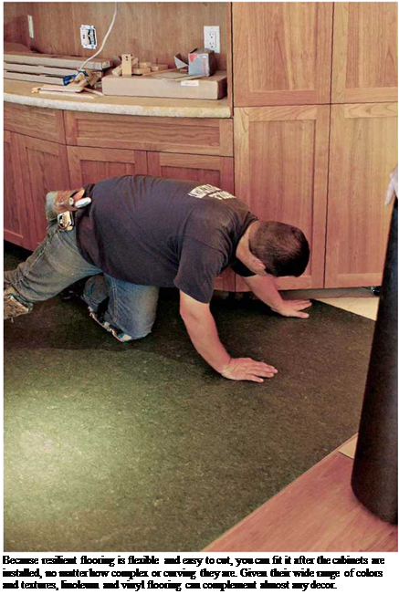
Подпись: Because resilient flooring is flexible and easy to cut, you can fit it after the cabinets are installed, no matter how complex or curving they are. Given their wide range of colors and textures, linoleum and vinyl flooring can complement almost any decor. Before filling panel joints and irregularities with a patching compound, use a wide spackling knife or drywall-taping knife to scrape off splinters. If the blade clicks against a nail or staple, use a nail set to sink the fastener below the surface.

Most resilient flooring makers specify a port­land cement-based patching compound, which may contain a latex binder. If you use any under – layment other than hardboard, fill and level the panel joints and surface imperfections. But don’t fill nail holes because if nails work loose, they’ll raise the patching compound as well, creating a bump in the flooring. Apply one or two coats of compound, feathering it out along the edges of the seam. If you’re careful, you won’t need to sand the compound.

Conclusion

From our earliest ancestors who created irrigation canals by scratching the ground to channel the water of a stream, to the appearance of the first technology, from the great engineering projects of Mesopotamia and China to the blossoming of the first great cities – civilization and hydraulics have always advanced hand-in-hand.

Technique, power and society

In numerous ancient civilizations, the legitimacy of those who govern – both in their own eyes and in those of the governed – rests on the social utility of their hydraulic projects. Technique and society are indissolubly linked.

Hammurabi of Babylon, conqueror of all of Mesopotamia, proclaims himself “lord of the city of Uruk” and immediately adds, as if to ensure the legitimacy of this domina­tion, that it was he who “allocated to these people the water of prosperity”. He nonethe­less owed his power to his weaponry – and to diplomacy. Yahdun Lim at Mari made the same kind of claim, as did many other leaders of the land of Sumer, all of whom associ­ated the legitimacy of their power and the glory of their reign with the hydraulic projects that they had effected.

A thousand years later, when Cyrus the Great entered Babylon, he legitimized his power in “raising the brick banks lining the city’s ditches”. Alexander, another great his­torical figure, acts no differently after having occupied Mesopotamia when he ensures that the canals are maintained and tears down the dams the Persians had constructed to block navigation. These technical acts are tantamount to acts of coronation. Was not the legend that grew up around Yu the Great, the pacifier of the Yellow River, the very legit­imization of central power in China? We have seen so clearly that in this land it was often hydraulic catastrophes that caused the fall of dynasties. In ancient Egypt, whose cultural and political stability make it somewhat of a special case, the sovereign is, even here, identified with the river from which all blessings come.

Guidelines for FAST Diagrams

Figure 10.1 depicts the diagramming conventions to be used in preparing a FAST dia­gram. The relative positions of functions as displayed on the diagram are also levels of activity. The FAST diagram is a horizontal graphical display based on system functions rather than system flowcharting or components. Level 1 functions, the higher-level func­tions, appear on the left side of the FAST diagram, with lower-level activity successively graphed to the right as shown. In most cases, when conducting a VE study, various levels of activity of verb-noun functions will be automatically suggested as the basic function of an item or a system.

The FAST diagram is just a tool. It is the process used in creating the diagram that is important, not the final diagram itself or its appearance. There is no such thing as a

“right” or perfect schoolbook solution that each diagrammer should be able to create, if he or she had perfect knowledge of the technique and theory. Yet if the diagram logic is logical to the diagrammer, it will normally be logical to a reviewer. And if it is not, then the FAST diagram will have served another purpose—communication of a misunderstanding in statement of the problem. That is also valuable to know. With these things in mind, consider the following guidelines in preparing a diagram:

1. Show the scope of the problem under study by two vertical dashed lines, one to the extreme left and one to the extreme right of the diagram. Everything that lies between the two scope lines is defined as the problem under study.

2. Every FAST diagram will have a “critical path of functions” going from left to right across the scope lines.

3. On that critical path should be found only required secondary functions, the basic function(s), and the higher-order function.

4. The higher-order function will lie to the immediate left of the left scope line.

5. The basic function(s) will always lie to the immediate right of the left scope line.

6. All other functions on the critical path will lie to the right of the basic function and will be the required secondary functions (not normally aesthetic or unwanted secondary functions).

7. Any “assumed” functions lie to the right of the right-hand scope line.

8. All other secondary functions the item performs will lie either above or below the critical path of functions. These functions can be required secondary functions, aesthetic functions, or unwanted functions.

9. If the function “happens at the same time as” and/or “is caused by” some function on the critical path, place the function below that critical path function.

10. If the function happens “all the time” the system is doing its work, place it above the critical path function to the extreme right of the diagram.

11. If there are specific design objectives or general specifications to keep in mind as the diagram is constructed, place them above the basic function and show them as dotted boxes.

12. All “one-time” actions are placed above the critical path and in the center area of the diagram.

13. All functions that lie on the critical path must take place to accomplish the basic func­tion. All other functions on the FAST diagram are subordinate to the critical path function and may or may not have to take place to accomplish the basic functions.

LAYOUT, STARTER ROWS, AND BEYOND

There are two places to install a starter row. The first and most obvious place is along a long wall. The second place is down the center of the room, which is recommended when rooms are wider than 15 ft., when rooms are complex, when several rooms converge, and when walls are out of parallel by 1 in. or more.

Flooring usually runs parallel to the length of a room, so start by measuring the width of the room at several points to see if the walls are par­allel. If the walls aren’t parallel, split the differ­ence eventually by ripping down the final row of boards on both sides of the room.

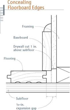
Use baseboards to conceal the expansion gaps. If baseboards aren’t thick enough to conceal the gaps, you may need to cut back the drywall as shown in "Concealing Floorboard Edges,” below.

Installing the starter row along a long wall. At

both ends of the room, measure out from the wall the width of a floorboard plus % in. for expansion. Snap a chalkline through those two points so you’ll have a straight line to align the starter row to. Place the groove edges of the first

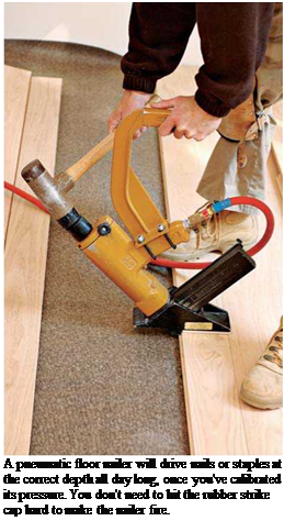
Подпись: A pneumatic floor nailer will drive nails or staples at the correct depth all day long, once you've calibrated its pressure. You don't need to hit the rubber strike cap hard to make the nailer fire.

image1011

When walls are out of square, baseboards or shoe molding may not be wide enough to cover the 3/4-in. gap wood floors require. In that case, trim the bottom of the drywall about 1 in. to gain additional space.

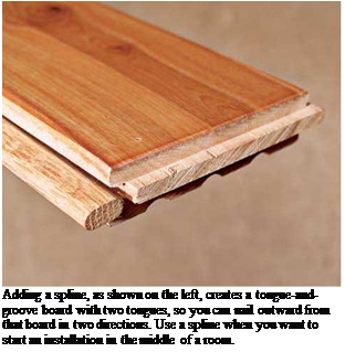
Подпись: Adding a spline, as shown on the left, creates a tongue-and-groove board with two tongues, so you can nail outward from that board in two directions. Use a spline when you want to start an installation in the middle of a room.

row toward the wall, so the boards’ tongues face into the room. If you pick straight boards for the starter row, successive rows will be more likely to stay straight. Face-nail the boards in the starter row, driving pairs of 6d or 8d nails every 10 in. to 12 in., and placing them in 1 in. from the boards’ edges.

If you use a pneumatic finish nailer to face – nail the boards, you’ll be unlikely to split them.

If you hand-drive the face nails, use a Me-in. bit to predrill for 6d spiral nails. In either case, sink the nail heads below the surface of the wood, and even­tually fill holes with wood putty. Next, use the pneumatic floor­ing nailer to blind-nail (nail through tongues) boards every 10 in. to 12 in. To further avoid splits, don’t nail within 2 in. to 3 in. of a board’s end. Once the starter row is secured, blind – nail subsequent floorboards till you reach the opposite wall and run out of room to use the pneumatic nailer.

Installing the starter row in the middle of the room. Measure out from both long walls to find the approximate center of the room. If walls aren’t parallel, the centerline should split the dif­ference of the measurements between the two walls. Snap a chalkline to indicate the centerline; line up the starter row to it. Because you don’t face-nail a starter course in the middle of a room, screw temporary blocks—scrap flooring is fine— along the chalkline to keep starter-row boards in place. Otherwise, they could drift as you drive nails through the tongues. Nail down five or six rows, before removing the temporary blocks.

Next, add wood splines (also called slip tongues) to the grooves of starter-row boards, which most flooring stores carry. Adding splines allows you to blind-nail toward the opposite wall as well. Glue splines to board’s grooves, using scrap flooring to drive the splines snug without damaging them.

Installing the rest is straightforward. To speed the installation and ensure that board ends are staggered at least 6 in. between rows, have a helper rack (spread out) floorboards so you can quickly tap boards into position with the flooring mallet and nail them down. Floorboards come in regular lengths from 12 in. to 36 in. So to create a random joint pattern, use board remnants with irregular lengths to start rows.

Continue blind-nailing boards every 10 in. to 12 in., checking periodically to make sure the
rows are straight. If milling irregularities or warping prevents boards from seating correctly, use a large flat screwdriver to lever the boards snug, as shown in the top left photo on the facing page. Set aside boards that are too irregular to use; professional installers typically order 5 per­cent extra to allow for warped or poorly milled boards and waste.

As you approach within a foot or two of the opposite wall or next to a base cabinet, you won’t have room to use the pneumatic flooring nailer, so switch to a pneumatic finish nailer. Nor will you have room to swing your flooring mallet, so use a pry bar to draw the boards’ edges snug. As you get within 6 in. to 8 in. of the wall, measure the distance remaining, including 3з4 in. for an expansion joint. In most cases, you’ll need to rip down the last row of floorboards. If they are less than 1 in. wide, first glue them to the next-to-the – last row and install the two rows as a unit. Or, if you’re installing floorboards of varying widths, rip down a wider board. The last row of boards should be face-nailed and glued to the subfloor as well. Finally, install prefinished transition pieces such as thresholds, reducer strips (strips that taper to accommodate differing floor heights) and so on. When you’ve sanded and finished the flooring, reinstall the baseboards.

Store extra flooring in a dry location. If the flooring has a warranty, file it in a safe place, along with the flooring’s code number and floor care information.

image1013

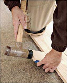
Using a piece of scrap to avoid damaging the tongues, drive the boards snug before nailing them. The friction between the tongues and the grooves will usually hold them during nailing.

image1014

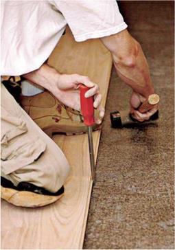
If boards are slightly warped or tongues and grooves are a bit swollen, use a thick screwdriver as a lever to draw them together. Hammer the screwdriver point into the subfloor to get some traction.


image1015

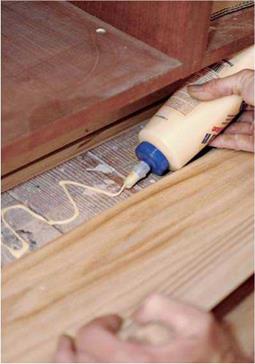
Glue the last row of boards, especially those at the base of a cabinet. Only one edge will engage the board next to it, and there’s often not enough room to drive nails.


image1016

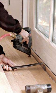
The first and last rows of tongue – and-groove floorboards are usually face-nailed, here with a pneumatic finish nailer. Draw boards tight with a flat board.


HEATING, VENTILATION, AND AIR CONDITIONING

Because HVAC system design is complex, judgement on system type, size, and location of ducts is often left to the expert – the HVAC subcontractor. But the builder should understand some basic facts to insure that the most efficient, cost-effective system available is being installed.

Select the most appropriate economical system according to home design, local climate, fuel availability, and market ^reference. If a ducted system is to be used, a concise guide is available тот the National Association of Home : Builders, 15th & M Streets, NW, Washington, DC 20005. Titled Residential Duct Systems, this guide describes the most efficient duct methods according to fuel, type of equipment, operating efficiencies, and relative cost.

Design starts with accurate heat loss calculations (and heat gain for cooling). This is the only real basis for selecting equipment and designing the system. Too often equipment is selected based on past experience and judgement.

But, since each home design is unique, the HVAC system should be tailor made for that home. Guidelines on how calculations are made are presented in the Residential Duct Systems manual mentioned above as well as in the Insulation Manual for Homes and Apartments, also available from NAHB.

The standard calculation procedure used in the HVAC trade is in Manual J. Load Calculation for Residential Winter and Summer Air Conditioning available from Air Conditioning Contractors of America, 1228 – 17th Street, NW, Washington, DC 20036.

Avoid the tendency to oversize HVAC equipment. Some believe that if a certain size equipment is adequate based on proper calculations, a size larger will be even more desirable. Since the incremental cost of upsizing appears not too excessive, it is tempt­ing to oversize. However, equipment based on sound heat loss-gain calcula­tions is almost always more efficient and uniform in heating and cooling than oversized units. Also, be aware of unit efficiency.

For each 1 /2-ton heatpump or air conditioning reduction, equipment and duct costs can be reduced by about $275. Wiring costs may also be reduced since a lighter circuit may be possible.

Downsized or redesigned duct systems will be possible in energy-efficient homes where HVAC equipment is smaller. In addition, the system will perform better since proper velocity and air flow will be maintained. Another standard guide for residential duct design is Manual D – Duct Design for Residential Winter and Summer Air Conditioning, from the Air Conditioning Contractors of America, 1228 17th Street, NW, Washington, DC 20036.

HEATING, VENTILATION, AND AIR CONDITIONING

In small, single-story homes with a central hall that abuts all living areas, consider using a dropped-hall ceiling plenum system. In this system, the hall ceiling and walls are drywalled as usual. Then another ceiling, dropped 6 inches to 8 inches below the con­ventional ceiling, is framed and drywalled, thus providing a plenum for air distribution.

High inside wall registers to each adjoining room are connected to the plenum by a short sheet metal boot through the wall. Although the system described has worked well in many installations, some local inspec­tors insist on sheet metal ducts within the ceiling cavity. If so, the system is still more cost effective than most.

The CABO One and Two Family Dwelling Code permits such "gypsum ducts" up to 125 degrees F., which would accommodate low output temperature equipment such as most heat pumps or electric furnaces. Fossil fueled equipment generally exceed this temperature limit.

Radial duct systems are often the simplest duct systems to install.

Branch ducts connect directly to the equipment plenum without trunks. Radial systems are typically installed where it is not necessary to conceal the duct work and where the equip­ment is centrally located. The basic simplicity of the system provides cost savings through reduced materials and less labor.

HEATING, VENTILATION, AND AIR CONDITIONING

In smaller, well-insulated homes where central air conditioning is not re­quired, electric baseboard heat with individual room thermostats offers significant construction cost savings, and depending on comparative fuel costs and availability, may offer operating cost savings because of the ability to "zone" heat the house.

Подпись: A downflow forced air heating and/or cooling unit maintains slight air pressure in the plenum, assuring uniform distribution of conditioned air throughout the building with few or no supply ducts. Studies have shown that the initial costs of the Plenwood system are typically about 10 percent less than conventional ducted systems. For more information on the Plenwood System, write the American Plywood Association, P.O. Box 11700, Tacoma, WA 98411.Подпись: Non-ducted range hoods cost $20 to $40 less, eliminate a scheduling problem, and are more energy-efficient than ducted systems. However, humidity control and indoor air quality should be considered.One very innovative heating/cooling system that has enjoyed some regional success is the underfloor heating/cool­ing plenum, being marketed by the wood industry under the name "Plenwood." Instead of using heating and cooling ducts, the entire under­floor space is used as a sealed – plenum chamber to distribute warm or cool air to floor registers in the rooms above.

Several of the JVAH builders used innovative HVAC systems to reduce costs. In Santa Fe and Phoenix, bathroom ventilation fans were eliminated, saving about $150 per unit in ventilation ana electrical wiring.

Подпись: EXAMPLES FROM THE DEMONSTRATION PROJECTSIn Crittenden County, Arkansas, the builder used the ductless dropped ceiling approach to air distribution in homes with central air conditioning.

In Christian County, Kentucky, a radial duct system was used instead of one large trunk line throughout the center of the crawl space with lateral ducts. This system saved an average of $125 per house.

The most innovative HVAC system built in the JVAH program was in Tulsa, Oklahoma, where the Plenwood system described earlier was installed. Wayne Hood used the underfloor area as a ductless return air plenum (See Footings and Foundation Section) with a pressure treated wood foundation. Hood estimated that foundation, floor and heating/cooling costs were reduced by a total of $1,470 per unit.

HEATING, VENTILATION, AND AIR CONDITIONING

Hand Tools

Nail guns are one of a framer’s most commonly used tools. They are also one of the most dangerous. Most framers can show you a scar from having shot themselves with a nail gun. Fortunately, many of these injuries are not serious. However, there have been instances where serious injury or death has occurred. Following are some very basic guidelines that will help you operate a nail gun safely. (Always familiarize yourself with the manufacturer’s complete operating instructions.)

• Wear safety glasses.

• Do not hold the trigger down unless you’re nailing.

• Be careful when nailing close to the edge. The push lever at the nose of the gun can catch the wood and allow the gun to fire without the nail hitting the wood, allowing the nail to fly toward whatever is in line with the gun.

• Always keep your hand far enough away from the nose of the nail gun so that if the nail hits a knot or obstruction and bends, it will not hit your hand.

• Never point a nail gun at anyone.

• Disconnect the air hose before working on the gun.

• Use a gun hanger when working at heights, or secure your air hose so the gun does not get dragged off or fall. (See “Nail Gun and Hanger" photo.)

• When nailing off the roof or high floor sheathing, move in a forward, not a backward direction to prevent backing off the edge.

• Move from top to bottom on wall sheathing so you can use the weight of the gun to your advantage.

Trainees are the most vulnerable to nail gun accidents. Make sure that when you are training new recruits on nailing with a nail gun, you formally instruct them on nail gun safety and the potential for accidents.

Circular saws have cut off many fingers. A healthy respect for them is the first step toward safety. Follow these basic guidelines (and the manufacturer’s operating instructions):

• Wear safety glasses when operating a circular saw.

• Always keep your fingers away from where the blade is going.

• Never remove or pin back the guard on the saw. The saw guard has a tendency to catch on many cuts, especially angle cuts, which makes it tempting to pin the guard back. Aside from the fact that it is an OSHA violation, a saw can become bound in a piece of wood, and “kick back." If the guard is pinned back, this can result in serious injury such as cuts to the thigh.

• Never use a dull blade. It will cause you to put excess directional force on the saw, which could cause it to go where you don’t want it to.

• Disconnect from power if you are working on the saw.

• When you are cutting lumber, make sure that one end can fall free so that the blade does not bind and kick back.

As the teeth of a circular saw speed around at almost 140 miles per hour, it becomes very dangerous if not used properly.

Miscellaneous hand tools also need to be used properly for safety. The following guidelines apply to many hand tools:

• Make sure all safety guards are in place.

• Keep your finger off the trigger of power tools when you are carrying them to prevent accidental starting.

• Keep tools properly sharpened.

• Store tools in the locations provided.

• Before working on power tools, unplug them or take out the battery.

• Replace worn or broken tools immediately.

• Never leave tools in paths where they can become a tripping hazard.

To use a powder-actuated tool, you need to be trained by a certified trainer. Following are some of the basics that you will learn:

• You must wear safety glasses.

• Hard hats and hearing protection are recommended.

• Never point a powder-actuated nail gun at anyone.

• Before you fire, make sure no one is on the other side of the material you are firing into.

• Do not load the firing cartridge until you are ready to use it.

• If there is a misfire, hold the tool against the work surface for at least 30 seconds; then try firing again. If the tool misfires a second time, hold it against the work surface again for 30 seconds; then remove the cartridge and inspect the gun. Soak the misfired cartridges in water in a safe location.

• Powder-actuated tools need to be placed firmly against the work, perpendicular to the work to avoid ricochet.

It’s also a good idea to say “fire" just before you pull the trigger, so the shot noise will not startle the workers around you.

Ladder extension

Interior and exterior stairs

The basic structure of the stair depends primarily on whether the stairway is to be located inside or outside and whether it is to be protected from the weather or not. The wood-stair details discussed in this chapter can be employed for either interior or exterior stair­ways, although the location will suggest basic detailing differences due to the fact that one is protected from the weather and the other isn’t.

Interior stairs—Interior stairs are usually more refined than exterior stairs. Interior stairways may be the showcase of a building and so are often located near the entry and used as a major circulation route. They may also provide the opportunity to connect more than one floor with natural light.

Exterior stairs—Exterior stairs (see 222) have the same minimum proportional requirements as interior stairs, but they are generally built less steep. The treads need to be deeper and risers shallower outdoors to make the stairs safer when wet or covered with snow or ice. Materials on exterior stairs must also be chosen with the weather in mind. Weather-resistant materials such as concrete, masonry, and metal are sound choices for stairs exposed to the elements. Heavy timber or pressure-treated wood is often chosen for a wood stair out of doors. Special attention should be paid to non­skid surfaces for treads exposed to the weather.

Some exterior stairs are supported directly on the ground, in which case they are usually called steps (see 223-225). Ground-supported steps follow the contours of sloping sites to provide easy access to porches or entrances or as connections between terraces and other landscape elements.

Control of Compliance with an SMA Mix Recipe

14.8.3.1 determination of the Operating compliance Level

The principle of fixing frequencies of control testing depends on the number of deviations found and has been adopted in the standard EN 13108-21. With an established level of requirements (X, Y, or Z), the frequency of sampling is variable, depending on the production accuracy of the asphalt plant (i. e., the number of devia­tions from a recipe).

14.8.3.2 Start in Control

The initial frequency of sampling depends on an established category of conformity (X, Y, or Z), so at first the frequency of sampling is as follows:

• Every 150 tons of a manufactured mixture (for level X)

• Every 250 tons of a manufactured mixture (for level Y)

• Every 500 tons of a manufactured mixture (for level Z)

Samples should be representative of the entire production; the relevant clauses of EN 12697-27 and EN 12697-28 should be taken into account.

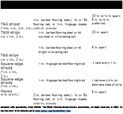
Floor Nailing Schedule*

Подпись: SIZE AND TYPE FLOORING SIZE NAIL TO USE SPACING T&G stripst (3/4 in. x К in., 27, in., 37, in.) 2-in. barbed flooring cleat,! 7d or 8d flooring nail, or 2-in. 15-gauge staples with 72-in. crowns! 10 in. to 12 in. apart; 8 in. to 10 in. preferred T&Gt strips (7 in. x 17 in., 2 in.) 17-in. barbed flooring cleat or 5d cut-steel or wire-casing nail 10 in. apart T&G strips (7 in. x 17 in., 2 in.) 17-in. barbed flooring cleat or 4d bright wire casing nail 8 in. apart Square-edge strips§ (5/i6 in. x 17 in., 2 in.) 1-in. 15-gauge barbed flooring brad 2 nails every 7 in. Square-edge strips§ (5/i6 in. x 17 in.) 1-in. 15-gauge barbed flooring brad 1 nail every 5 in. on alternate sides of strip Planks (4 in. to 8 in.) 2-in. barbed flooring cleat,!- 7d or 8d flooring nail, or 2-in. 15-gauge staples with 7-in. crowns! 8 in. apart Adapted, with permission, from NOFMA: The Wood Flooring Manufacturers Association, all rights reserved, © 2004. To see the chart in its entirety go to www.nofma.org/installation3.htm. Подпись: t Tongue-and-groove (T&G) flooring is blind-nailed on the tongue edge, with face-nailing required on the starting and finishing runs. t NOFMA Hardwood Flooring™ must be installed over a proper subfloor. Use 1 1/2-in. fasteners with a 3/4-in. plywood subfloor on a concrete slab. A concrete slab with sleepers every 12 in. on center does not always require a subfloor. § Square-edge flooring is face-nailed. ing or air-conditioning so indoor conditions will be close to normal (60°F to 70°F) for a week before installing flooring. Open the bundles of wood flooring and allow them to acclimate indoors for 72 hours before installing them.

Use a moisture meter to check interiors if your region has high humidity. Home centers and elec­tronics stores carry reliable, inexpensive meters. Ambient humidity indoors should be 35 percent to 55 percent; if readings are higher, consider installing a dehumidifier. Also check the moisture content (MC) of wood subfloors and flooring, using a moisture meter with probes. Typically, wood flooring’s MC is 6 percent to 10 percent.

The subfloor’s MC should not vary more than 4 percent from that of the flooring’s.

If you’re installing floors over a basement or crawl space, check the humidity of that area, too. If it’s too high, correct any contributing factors before installing wood floors; high humidity also encourages mold. Crawl spaces with dirt floors
should be covered with plastic and sealed to limit moisture and air infiltration, as described in Chapter 14.

Survey subfloors to make sure they’re solid, flat, and clean. If floors are excessively springy, stiffen them by adding blocking between the joists, adding plywood or OSB (oriented strand board) panels over existing subfloors, or sistering new joists to old ones, as described in Chapter 8. In older houses, floors are rarely level; so if they’re solid, it’s more important that they be flat—with­in 12 in. per 10 ft. Use a rental edging sander or a woodworker’s belt sander with coarse sandpaper to lower high spots; use strips of building paper (15-lb. felt paper rather than rosin paper) or wood shims to build up low spots. In general, masonry floor-leveling compound is too inflexible to use beneath wood flooring because flooring nails will fragment it and board flexion will frac­ture it.

If you notice protruding nail heads, not enough nails, or squeaky spots, correct these con­ditions now. Squeaks can usually be silenced by screwing down subflooring to joists near the squeak or by nailing it down with ring-shank or spiral nails. Vacuum and sweep the floor well. If the floor is over an occasionally damp basement or crawl space, staple 15-lb. building paper to the subfloor, overlapping roll seams by 6 in. However, don’t bother with building paper if the subfloor areas are dry or if the floor is on an upper story.

Finally, remove the baseboard molding if you can do so without damaging it. Baseboards hide the expansion gap between the perimeter of the flooring and the base of the wall. At the very least, install a piece of quarter-round shoe mold­ing to cover the gap if you can’t remove the base­boards. If door casings are already installed, undercut (trim the bottoms of) each side jamb, by the thickness of the flooring; an undercut saw is specially designed for this task. Remove door­way thresholds if they’re nailed down. But if they’re glued down or set in mortar, simply butt the flooring to them.

EQUIPMENT

Sawdust or debris trapped under a board can mean uneven, loose, or squeaky floors later on, so be obsessive about keeping subfloors clean as you install flooring.

Installation tools include safety glasses, hearing protection, kneepads, radial-arm saw or small table saw, hammer, nail set, tape measure, chalk­line, flat pry bar to remove trim, large flat-bladed screwdriver to draw board edges tight to each other, flooring mallet, and a manual or pneumatic

Подпись: As you install strip flooring, use wood from several different bundles or cartons to ensure a varied mix of color and grain. If strips are noticeably lighter or darker, distribute them throughout the floor to avoid obvious, odd-color sections. Stagger board ends in adjacent rows by at least 6 in. because random joint patterns will be visually less intrusive. llll

flooring nailer. For the little bit of face-nailing to be done, use a pneumatic finish nailer; if you haven’t got one, use a Иб-in. bit to predrill holes for the face nails. You’ll need white glue to secure floorboards under toekicks and in other odd spaces where it’s difficult to reach with any nail­er. Finally, rent a shop vacuum if you don’t own one. And be sure to have a good-quality broom and a dustpan.

Pneumatic flooring nailers are more expensive than manual nailers, but they don’t depend on your strength to drive flooring nails to the correct depth. Nailers aren’t foolproof, though. Take a sample of the flooring to the rental company to ensure that the pneumatic nailer will correctly engage the flooring edge profile. That is, the tool may need an adapter-fitting or – plate to avoid damaging the boards’ tongues. On-site at the start of the job, calibrate the nailer’s pressure by nailing a "practice row” of flooring to the sub­floor. Typically, pneumatic nailers are set at 70 psi (pounds per square inch); adjust the pres­sure up or down till the tool sets nails correctly, as shown in "How Deep Can You Sand?,” on p. 488. Once the setting is correct, pull up the practice row.