Preparing Pavement Facilities

The existing pavement facilities should be prepared prior to placing the mixture of a wearing course. This preparation should result in the following:

• Appropriate, tight, and durable bonding between asphalt course and facilities (e. g., with the use of suitable polymer modified asphalt tapes [Figure 10.7])

• Protection against damage or infiltration of excess asphalt mixture (e. g., around a drain or manhole)

10.2.5 Preparing Edges of the Courses

The edges of the course should also be prepared. The selected method should ensure durable joints at the transverse and longitudinal edges. Most previous experiences have proved the poor effectiveness of traditional methods like applying hot binder,

Preparing Pavement Facilities

image100FIGURE 10.8 PMB tape for sealing pavement joints (a) when bonding with a layer edge and (b) after application. (Photos courtesy of Slaskie Kruszywa Naturalne sp. z o. o., Poland.)

covering with emulsion, and other similar techniques. As in other cases, PMB tapes (Figure 10.8) put on manually or special PMB compounds spread mechanically (Figure 10.9) have been recommended.

REPLACEMENTS FOR BRIDGES

5.9.1 Introduction

America’s transportation infrastructure—particularly the Interstate Highway System— is past its original anticipated design life and its age is showing. The age of the system coupled with high user demand and limited financial resources requires innovative thinking from the design engineer. One solution frequently utilized is the replacement of deficient bridges with prefabricated structures. The prefabricated alternative is typi­cally less expensive to construct, easier to maintain, and can be built with significantly less service disruption to the traveling public.

This approach can be utilized for stream crossings and for grade separation struc­tures. The systematic approach for selecting an appropriate structure is similar for both applications. The designer must determine an appropriately sized structure; deter­mine if any of the existing structure will be reused; determine how much of the struc­ture will remain in place; assess the constructability of the proposed replacement structure; and determine the structural capacity of the proposed structure.

Proportion

If these principles are starting to seem a lot like common sense, it is be­cause they are. It is in our nature to seek out the sort of order that they prescribe. Honest structure and simple forms strike a chord with us because they are true to nature’s law of necessity. Sound proportions strike a chord, too. Certain proportions seem to appear everywhere — in sea shells, trees, geodes, cell structure, and all of what is commonly called "the natural world.” That these same proportions continually turn up in our own creations should not seem too surprising or coincidental. We are nature, after all, and so our works are bound to contain these natural proportions.

Proportioning is one of the primary means by which a building can be made readable. Repeated architectural forms and the spaces between them are like music, the pattern (or rhythm) of which we understand because it is al­ways with us. We intuitively understand good proportions because they are a part of our most primal language.

On the most conscious level, good proportion is achieved by first choosing an increment of measure. Making such a seemingly arbitrary decision can be made easier if meaning is imposed on it. Ancient civilizations created sys­tems of measure based on human and geodetic significance. A Mediterra – nian precursor to the foot we use today was 1/360,000 of 1/360 (one degree) of the circumference of the earth. It was also related to the conventional calendar containing 360 days of the year plus five holy days, and it was 1/6 the height of what were viewed as ideal human proportions. The eighteen – inch cubit (distance from elbow to longest finger tip) and the yard (1/2 of the total height) also relate to this canon. We have inherited a measuring system imbued with meaning that relates us to our environment. Our buildings are literally designed to embody the characteristics of the Self.

Today, plywood is milled to 4’ x 8’ pieces; lumber comes in 6’, 8’, 10’, 12’ and 16’ lengths; metal roofing is typically 3’ wide, and most other building materi­als are similarly sized to fit within this one foot system of measure. Great ef­ficiency can be achieved by keeping this in mind during the design process. A large share of bragging rights deservedly go to a designer whose structure has left little construction waste and has required relatively few saw cuts. Simplified construction is nearly as much the aim of subtractive design as simplified form and function are.

The unit of measure we use to compose a harmonious design can be more than just linear. In Japan, a two-dimensional increment called the "tatami mat” is often used. It is an area of three by six feet (the Japanese foot, or shaku, is actually 11.93 of our inches). This area is meant to correlate with human dimensions. The Japanese saying, "tatte hanjo, nete ichijo,” trans­lates as, "half a mat to stand, one mat to sleep.”

Once an increment has been chosen, be it a foot, yard, cubit, tatami mat or a sheet of plywood, we can begin to compose a home comprised of simple multiples and fractions of the unit. This process should be fairly intuitive. Each one of us will compose somewhat differently, but our underlying prin­ciples are the same. These principles are not arbitrary, but the same that govern the composition of all natural things.

Dee Williams’ house in Olympia, WA

Tunnel Liner Plates and Rib and Lagging

Steel tunnel liner plate and steel rib and lagging are flexible structures placed by a tunneling operation. Like other flexible structures, they are designed to deflect verti­cally under load so that the lateral side pressure will be established and essentially uniform radial pressure will develop about the perimeter of the structure. Because these structures are used in tunneling operations, however, under most circumstances it is not necessary to design for the complete prism load. The AASHTO Standard

TABLE 5.27 Average Values of Modulus of Soil Reaction E’ for Deflection Calculations for Flexible Pipe

E’ for degree of compaction of bedding, lb/in2

Slight,

Moderate,

High,

Soil type—pipe bedding

< 85% Proctor,

85-95% Proctor,

> 95% Proctor,

material (Unified Classi-

< 40% relative

40-70% relative

>70% relative

fication System)*

Dumped density

density

density

Fine-grained soils (LL>50)f Soils with medium to high plasticity CH, MH, CH-MH

No data available; consult otherwise use E’ = 0

a competent soils engineer;

Fine-grained soils (LL<50)

Soils with medium to no plasticity CL, ML, ML-CL, with less than 25% coarse­grained particles

50 200

400

1000

Fine-grained soils (LL<50)

Soils with medium to no plasticity CL, ML, ML-CL, with more than 25% coarse-

100 400

1000

2000

grained particles Coarse-grained soils with fines

GM, GC, SM, SC contains more than 12% fines

Coarse-grained soils with little

or no fines

GW, GP, SW, SP£ contains less than 12% fines

200 1000

2000

3000

Crushed rock

1000 3000

3000

3000

Accuracy in terms of percentage deflections§

±2 ±2

±1

±0.5

Conversion: 1 lb/in2 = 6.895 X 10 3 MPa.

Note: Values applicable only for fills less than 50 ft (15 m). Table does not include any safety factor. For use in predicting initial deflections only; appropriate deflection lag factor must be applied for long-term deflections. If bedding falls on the borderline between two compaction categories, select lower E’ value or average the two values. Percentage Proctor based on laboratory maximum dry density from test standards using about 12,500 ft – lb/ft3 (598,000 J/m3) (ASTM D698, AASHTO T-99, USBR Designation E-11). 1 lb/in2 = 6.9 kN/m2.

*ASTM designation D2487, USBR designation E-3.

fLL = liquid limit.

$Or any borderline soil beginning with one of these symbols (i. e., GM-GC, GC-SC).

§For ±1% accuracy and predicted deflection of 3%, actual deflection would be between 2% and 4%.

Source: From American Society of Civil Engineers, J. Geotech. Eng. Div., January 1977, pp. 33-43,

with permission. (Based on Amster K. Howard, “Soil Reaction for Buried Flexible Pipe,” U. S. Bureau of Reclamation, Denver, Colo.)

Tunnel Liner Plates and Rib and Lagging

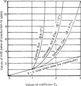
FIGURE 5.41 Diagram for coefficient Cd for load calculations for tunnels. ф is soil friction angle. (From Standard Specifications for Highway Bridges,

American Association of State Highway and Transportation Officials, Washington, D. C., 2004, with permission)

Specifications for Highway Bridges state that the earth pressure on a tunnel liner can be determined from the following equation:

W£ = CdlyS (5.56)

where WE = earth pressure at the crown, kip/ft2

Cdt = load coefficient for tunneling (from Fig. 5.41)

7 = unit weight of soil, kip/ft3 S = tunnel diameter or span, ft

The tunnel liners act in compression caused by ring thrust. If a structural member with significant stiffness is used, the effects of ring flexure must be included because the flexural stress may reduce the capacity of the member to carry load.

The design of tunnel liners generally consists of designing the liner for joint strength, wall buckling, and minimum stiffness for installation. The analysis of steel ribs with lagging is a fairly straightforward procedure. The steel ribs are generally placed at 4-ft (1.2-m) intervals on centers. The lagging must carry the load between these and is designed for moment and shear over the 4-ft (1.2-m) span. The load per linear foot may be taken as that for tunnel liner plate. The ribs must be designed to withstand the load transferred from the lagging. The stress in the steel ribs should include the effects of both flexure and thrust. The use of precast concrete tunnel liners as an initial support is
rare. The analysis is complex, but may be aided by the use of moment-thrust interaction diagrams. (See Standard Specifications for Highway Bridges, AASHTO; R. V. Proctor and T. L. White, Earth Tunneling with Steel Supports, Commercial Shearing, Inc., 1977; and T. D. O’Rourke, Guidelines for Tunneling Design, ASCE, 1984.)

Redox Potential (in-situ)

The redox potential, i. e. a measure (in volts) of the affinity of a substance for elec­trons compared with hydrogen, may also be determined in the field using electrical, hand-held equipment, this time employing an inert oxidation-reduction electrode.

7.5.2 Electrical Conductivity

Electrical conductivity is typically measured in-situ, being an important, yet sim­ple, indicator of pollution since the ability of water to conduct electricity increases as the proportion of dissolved ions increases. It can be measured directly through the insertion of probes and the resistance (or conductivity recorded) or indirectly through air-coupled “aerials”. However, because there are so many factors that affect electrical conductivity (e. g. presence of metals, saturation), it is normally best to use conductivity techniques as means of locating areas of anomalous response. These can then be investigated by alternative techniques to discover whether pollution is the cause and, if so, its degree and type.

Chapter Seven

LAYOUT

Layout is the written language of the framer. If the lead framer on the job “writes" clearly, then the framers reading the layout will be able to understand and properly perform the work. It’s important to include enough information in the layout so that there aren’t any questions. Layout language has been developed by framers over the years, and there are some variations. The version described in this book is quite typical. Feel free to make any changes that reflect practices in your area. If you need to explain something about the layout that isn’t shown in this chapter, either write it out on the plates in plain language, or explain it to the person who will do the framing.

Layout for framing requires bringing together the desires of the owner, the written instructions of the architect and engineer, instructions from the builder and/or superintendent, and materials from the supplier-then writing these instructions on job-site lumber in a legible manner so that the framers can build the walls, floors, and roofs without continuous interpretation. This chapter describes this process and explains the written words and symbols the lead framer uses.

The approach you use will depend on the size of the job, the area of the country you are working in and, most of all, the style of the person who taught you framing layout. This chapter presents a common style of layout, with some variations. Any style you use is good, as long as the framers can read and understand it, and you have provided all the information they need to frame the building completely.

Wall plates positioned vertically for layout

Wall Layout

On many jobs, the basic skeleton of the walls is built, and then the blocking, hold-downs, and miscellaneous framing are filled in as a later operation. There are some disadvantages to installing miscellaneous framing after the basic framing. For example, you may have to notch around wires and pipes. You may even have to come back and set up a separate operation after you have already left the job site. This chapter describes a system that includes everything possible in the layout, so the walls can be framed, complete, all at one time. To do this takes organization and pre-planning, which includes gathering all the information you need before you do the layout.

The positioning of the top plate and bottom plate for layout detailing is a variable that depends on personal preference and the type of operations.

The plate can be positioned vertically so that the Ш" width is on top, which makes it easy for marking on the plate. The plate can also be laid flat (horizontally) on top of the chalk lines so that the plates are in the same position as when the walls are standing. This system makes it easy to keep the walls in the proper position, particularly when you have angled walls. A third option (for some exterior walls
only) is to position the bottom plate where it will be once the wall is standing, then tack the top plate to it, hanging over the side. This system works well if you want to attach the bottom plate to the floor and then stick-frame the wall.

The layout language varies, but all layout styles are similar. The chart on page 138 shows the basic layout language. Page 144 shows additional language. Although the parts of the walls are typically the same in different areas of the country, quite often they are referred to by different names. For example, a backer is also known as a channel or partition. Even the term “layout" can have different meanings. Sometimes layout is understood to be the total process of chalking the lines for the wall locations (snapping), cutting the plates, and writing the layout language on the plates (detailing). It is not important what terms are used, as long as there is clear communication.

Wall layout is the process of taking the information given on the plans and writing enough instructions, in layout language, on the top and bottom plates so the framer can build the wall without asking any questions.

Following is some general information that must be considered before starting. Unless otherwise noted, all layout discussions will assume 2 x 4 studs at 16”

O. C. (on center).

Where possible, we want joists, studs, and rafters to rest directly over each other.

Before layout is started, establish reference points in the building for measuring both directions of layout and use those points for joist, stud, and rafter/truss layout throughout the building.

Check the building plans for a special joist plan or rafter/truss plans indicating layout.

Select a reference point which allows you to lay out in as long and straight a line as possible, and which ensures that a maximum number of rafters/trusses are directly supported by studs.

Wall Layout Steps

1. Spread the top plate and bottom plate together in chalk lines. If a plate is not long enough, cut the top plate to break on the middle of the stud and four feet away from walls running into it.

2. Place plates in position with chalk lines.

3. Lay out for backers from chalk lines.

4. Lay out stud trimmers and cripples for windows and doors.

5. Lay out studs.

Chalking Lines

“Chalking lines" is the process of marking on the subfloor where the walls are to be placed. Red chalk makes a permanent line and is easily seen. Blue chalk can be erased and is good to use if the lines might have to be changed. Using different colors allows you to distinguish between old and new lines.

Before chalking, when possible, check foundation and floor for square. Walls must be square, plumb, and level. If necessary, adjust your chalk lines accordingly.

Measurements for chalk lines are derived from wall dimensions as given in the plans. If the plans show finished walls, be sure to subtract the appropriate amount to get your framing measurements.

Divide Circumference for Treads

Draw lines from points A & B to the point where the bisecting line intersects the circumference (at point C) creating half lines.

2. Draw line from the radius origin to the circumference (at point D) passing through the mid point of the half line.

Stair wall lines Two established points Radius origin

3. Draw quarter lines by drawing lines from points B and C to point D.

4. Continue dividing lines in half until all tread widths are found.

In-situ Measurements

To measure pH in-situ, so-called pH testers (for a rough estimate of the pH value) and pocket (portable) pH meters are used (Fig. 7.9). Periodic calibration of the in­strument is required.

The determination of pH is very fast and reliable when a combined glass elec­trode is used. It enables an automatic measurement over long time intervals with the accuracy of ± 0.01 pH units. The glass electrode can be used even in strongly acidic and alkaline solutions, and also in the presence of oxidizing or reducing substances. It must be constantly immersed in water. With time, all glass electrodes deteriorate due to alkali leaching from the surface layers.

7.5.1 Introduction

When collecting a sample of water, certain principal variables that are prone to more or less rapid change upon sample storage must be measured in-situ. These variables characterize the status of the water at the time of sampling. These variables com­monly include electrical conductivity, pH, temperature, redox potential, and some­times also total hardness, turbidity, salinity and dissolved oxygen. Among the in-situ variables, electrical conductivity determination gives the most important informa­tion about water quality since it gives an indication of the salts dissolved in water.

Ion selective electrodes provide, in principle, a method for users to determine the concentrations of many ions. However, the instruments need careful (and often repeated) calibration to reference concentrations and washing in a buffer solution between successive readings. This makes their routine use on-site somewhat prob­lematic and prevents their sensible use as remote instrumentation. For this reason further details of these instruments are given in Section 7.6.2.

Choosing an Electrical Tester

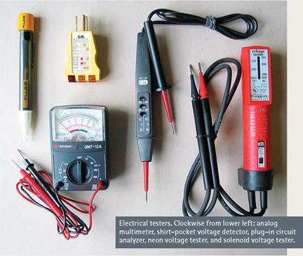
Testing to see if an outlet is energized is so critical to professional electricians that there are scores of specialized testers to choose from, some of which cost hundreds of dollars. Fortunately, amateur electricians can get a reliable tester for less than $30. Here are five types:

► Neon voltage testers are inexpensive and versatile. Insert the probes (prongs) into the receptacle slots or touch them to the screw terminals or to a metal outlet box to see if the unit is hot (energized). Buy quality: Better neon testers have insulated handles, whereas cheapies have bare metal probes so short that you risk shocking yourself when using them.

► Plug-in circuit analyzers can be used only with three-hole receptacles, but they quickly tell you if a circuit is correctly grounded and, if not, what the problem is. Different light combinations on the tester indicate various wiring prob­lems, such as no ground, hot and neutral reversed, and so on. Quite handy for quick home inspections.

► Shirt-pocket voltage detectors give a reading without directly touching a conductor. Touch the tool’s tip to an outlet, a fixture screw, or an electrical cord, and the tip glows red if there’s voltage present. Because they depend on battery power, voltage detectors are somewhat less reliable than other options, but all in all, it’s an ingenious tool.

► Solenoid voltage testers (often called "Wiggy’s") test polarity, AC, and DC voltage from 100 volts to 600 volts. Most models vibrate and light a bulb when current is present. Solenoid testers don’t use batteries, so readings can’t be compro­mised by low battery power. However, because of their low impedance, solenoid testers will trip GFCIs.

► Multimeters, as the name suggests, offer precise readings in multiple scales, which you select beforehand, although some models are autoranging (they select the correct scale). Extremely sensitive, they can detect minuscule amounts of current. Better models test AC and DC voltage, resistance, capacitance, and frequency.

image474

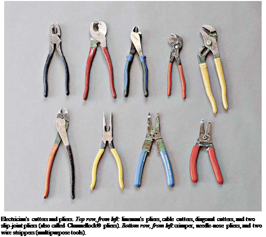
Подпись: Electrician's cutters and pliers. Top row, from left: lineman's pliers, cable cutters, diagonal cutters, and two slip-joint pliers (also called Channellock® pliers). Bottom row, from left:crimper, needle-nose pliers, and two wire strippers (multipurpose tools).

AND TRIMMERS

Now it’s time to cut some of the parts that make up the wall, beginning with the window and door headers and the rough sills. Recall from Chapter 3 that headers are needed at window and door openings to transfer the load of the building around these elements to the foundation. This wasn’t always done in old houses, so walls often

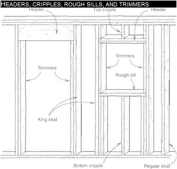
Подпись: HEADERS, CRIPPLES, ROUGH SILLS, AND TRIMMERS

sagged and doors and windows became hard to open because of all the weight put on them. Frequently, part of a remodeler’s job is to open up old walls and cut in solid headers over every door and window.

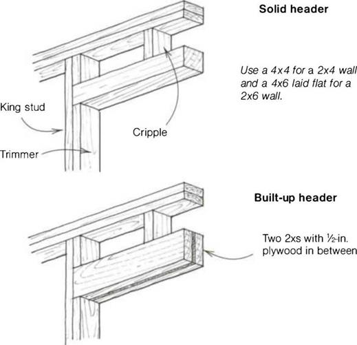
Ordinarily, the distance from the floor to the bottom of the door or window header is б ft. 10 in. Cripple studs (called cripples) are used to fill in the short space between the top of the header and the top plate, or between the bottom of a window opening and the bottom plate. Trimmer studs (called trimmers), nailed to the inside of the studs that border each end of headers, support the headers at the correct height (see the drawing above).

Cutting headers and rough sills

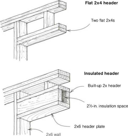
There are different types of headers for different applications. Solid headers (typically a 4×4 or a 4×6) are sometimes used, but more often than not, the headers are built up by sandwiching У2-ІП. plywood between a couple of 2xs. Flat 2x headers can be used for openings in nonbearing walls. Some builders like to put in double flat headers to make sure they have solid nailing for door and window trim. Or you can make a box header that can be filled with insulation to guard against heat loss (see the draw­ing on p. 108).

Outside walls are normally considered to be weight-bearing walls. Interior walls can be bearing or nonbearing, depend-

Подпись: FOUR TYPES OF HEADERSAND TRIMMERSAND TRIMMERSing on whether they carry weight from above. If you are using manufactured trusses for the roof, all interior walls are usually nonbearing, which makes it pos­sible to use the flat 2x for interior headers. In houses without roof trusses, joists and even roofs might be supported by an interior wall. Such walls are bear­ing walls and need larger headers to support the weight.

I’m often called on to remove a wall to make a room larger, so it’s important to know about bearing walls. The easiest way to check if a wall is bearing weight is to look in the attic to see whether joists or roof rafters are supported by it. Most walls can be removed, but a bear­ing wall must be replaced with a beam to support the weight. Of course, another owner may come along later who wants smaller rooms, making work for the next generation of carpenters.

The standard length of a header for doors and windows is 5 in. over the rough-opening size. Thus the header for a З-ft. opening is 41 in. The extra 5 in. leaves 3 in. for a 1 Уг-іп. trimmer on each side, 1Уг in. for а 3/нп. jamb on each side, plus 14 in. to plumb the trimmers. When using prehung doors, cut the headers 51Л in. longer for greater ease in installing the jamb.

Rough-opening sizes for aluminum and vinyl-clad window frames generally are 3 in. wider than the rough-opening size of the window. So, for a 3/6 window, cut the header 45 in. long. The extra 3 in. leaves space for a 1 Уг-іп. trimmer on each side plus enough room to set the window. Window frames are actu­ally У2 in. smaller than their nominal size. So a 3/6 window, for example, is usually 3 ft. 51/2 in. wide. Once set in the rough opening, the frame is nailed on with a 1/4-in. clearance on all sides. This gap is closed in by drywall or wood trim. Rough windowsills are cut to the same length as the corresponding header.