Author Testimonials

Paula Baker-Laporte

If someone had told me in the early years of my career that I would be writing a technical “how to” book about healthy homes, I would have looked at them with total incredulity! I would have explained that, as an architect, my main concerns were with the creation of beau­tiful and interactive spatial forms and that my aspirations were artistic rather than technical. It seems that fate had a different course for me. I joined the ranks of the chemically sensitive.

In retrospect, the roots of my illness can be traced back to formaldehyde overexpo­sure that I suffered when for a short period I lived in a brand-new mobile home. Working in standard residential construction, I found that my symptoms became severely aggra­vated whenever I visited a jobsite because of the prevalence of this toxic chemical in con­ventional construction materials. Erica Elliott, my friend and physician, diagnosed my con­dition and helped me get back on my feet, and it was through her that I first heard of healthy building. She told me of the alarming number of chronically ill patients consulting with her who were diagnosed with MCS. For many, the primary cause of illness was exposure to mul­tiple toxins in the home.

Even though I specialized in residential ar­chitecture, I had to admit I knew little about the health implications of standard home con­struction. While working with Erica to design her home, I began intensive research into this new frontier in architecture and building. It was then that my personal and professional life took a new direction.

Once I learned the facts, I could never again allow certain products, techniques, or equipment to be used in projects with which I became involved. I understood the health threats they posed to my clients, other inhab­itants, construction workers, and the planet. In my efforts to learn everything I could about healthy building, I came across a body of infor­mation translated from the original German called Bau-Biologie. Bau-Biologie advocates an environmentally sustainable approach to healthy building, in part through the use of natural, unprocessed building materials.

I used these principles when designing a new home for my family. Our home has a timber frame and clay/straw wall system. My husband and builder, Robert Laporte, intro­duced this building system to me when I first met him at a natural building workshop he was leading. Our home has earth plasters and earth and stone floors, and is heated primarily by solar heat and a masonry oven. The electri­cal wiring is in metal conduit. My own health has improved steadily, partly as a result of the clean and vital environment afforded to me by our natural home and unpolluted surround­ings. Although the bulk of my professional design work now incorporates alternative nat­ural building systems, I realize that the major­ity of people planning a new home do not have access to alternative materials and methods of construction. I also realize that, for some chemically sensitive individuals, many nat­ural materials can elicit symptoms as readily as synthetic ones do. For these reasons, much of the information in this book is geared to­ward making conventional building practices healthier.

A healthy home is far more than a home that is free of toxins. It must safeguard the residents on many other levels, described throughout this book. As a result of my re­search, my goals as an architect have grown. To truly nurture us, our buildings must not only be beautiful. They must also be healthful and conceived with mindfulness of our lim­ited planetary resources. The same building design can destroy human health or enhance vitality. The difference lies in the materials and construction methods we choose.

Erica Elliott

My involvement with indoor air quality is­sues began in 1991, when I went to work for a large medical corporation as a family physi­cian. The building housing the clinic was new and tightly sealed, with nonoperable windows and wall-to-wall carpeting. Previously in ex­cellent health, a world-class mountaineer and marathon runner, I began to develop unex­plainable fatigue. After several months, more symptoms developed, including rashes, burn­ing eyes, chronic sore throat, and headaches. The symptoms subsided in the evenings after I left the workplace, only to return when I reen­tered the building.

By my second year of employment, I had developed persistent migraine headaches, muscle and joint pains, insomnia, confusion, lack of coordination, memory loss, and mood swings. By then the symptoms had become permanent, continuing when I was away from my workplace on weekends. My physician col­leagues were puzzled by my symptoms. Some felt I was suffering an unusual manifestation of depression and would benefit from anti­depressant medication. These medicines were not helpful and only masked the problem.

I finally had the good fortune to find a physi­cian trained in environmental medicine who believed I had nervous and immune system damage related to chronic, low-level exposure to poorly ventilated toxins in the workplace.

By the time I resigned my position on the staff of the clinic and the local hospital, I had a full-blown case of multiple chemical sensi­tivity, also known as environmental illness. Most synthetic chemicals commonly found in the modern world, even in minute amounts, caused me to have adverse reactions to such a degree that life became a painful ordeal. With diligent avoidance of toxins, abundant rest, detoxification therapies, and other measures, my life began to stabilize.

Since very few physicians are trained in toxicology and environmental medicine, I im­mersed myself in this field of study, to help myself as well as others. It wasn’t long before my practice consisted primarily of patients with immune dysfunction, including multi­ple chemical sensitivity, autoimmune disease, chronic fatigue syndrome, fibromyalgia, and severe allergies. I was struck by the number of patients who dated the onset of their symp­toms to a move to a new home or to the re­modeling of a school or office. They invariably had been to many doctors who treated them for conditions such as allergies, asthma, sinus­itis, and depression. The underlying causes were not identified. By the time the correct diagnosis was made, the patients’ immune systems were often severely, sometimes irre­versibly, damaged.

It was during my own recovery that I de­cided to build a home using nontoxic building materials. Paula Baker-Laporte was my archi­tect, patient, and neighbor. Together we began researching various available products and as­sociated health effects. Shortly thereafter we had the pleasure of meeting John Banta, and a fruitful collaboration began.

Technology for eternity

How many achievements called “eternal” survive the civilization, or even the regime, under which they were created? Perhaps not many, but certain of the hydraulic works of Antiquity have survived their origins. The canal connecting the Nile River and the Red Sea – built by the Pharaoh Necho, finished by the Persian Darius, perfected by Ptolemy, the successor of Alexander, and renovated by the Emperor Trajan, then by the Umeyyade caliphs – functioned, though surely with a few interruptions, for an “eterni­ty” of thirteen centuries. We will have to come back a thousand years from now to see if our Suez Canal, descendent of the Necho canal, is still there………………………………………………………………………………………

The great irrigation systems and several water allocation plans of ancient China, as well as dams in the Armenian kingdom of Urartu, in Roman Spain, and in Arab Andalusia, are still in operation today. Others have disappeared even before seeing prac­tical use – like the Sadd el-Kafara dam project attempted by the Pharaohs of the Ancient Empire south of Memphis, reflecting missed opportunities for innovation and effective­ly stalling technical progress in Egyptian dams for several centuries. Other such dam projects were useful for a period, then fell into ruin, like the large Maryab dam in the land of the queen of Sheba, today reconstructed to be almost identical to the original by the modern state of Yemen. Other such dams that could have endured were abandoned, like the one built six thousand years ago by anonymous refugees, likely townspeople fleeing some unknown menace in the black basalt desert of Jordan. To survive in this desolate land they built, at Jawa, the first known dam in the history of humanity, before abandoning it to flee to some unknown destination.

Civilizations die. Often their works die with them. But their technologies survive. We are the inheritors of the hydraulic innovations of the millennia, whether they came to us through the work of some scholar who described them in writing that was subse­quently recopied and translated, or whether they came to us slowly through the random process of migration and commercial exchanges. Yes, these innovations have come down to us, who are depleting our groundwater resources, who are setting the stage for future water wars. The ancient water technologies are part of the patrimony that our children will so urgently need.

Design Life

The first task one must accomplish in performing an LCC analysis is to determine the period of time for which the analysis of accumulated costs is to occur. This will usually be designated the project design life. The life span of the facility to be analyzed (a bridge, pavement, or culvert pipe) must be determined, together with the associated maintenance and rehabilitation costs. Another consideration that must be addressed is the realization that individual life spans of components of a system may be quite different. For example, in considering a highway system, the life of a bridge will likely be much longer than the life of a pavement. In considering a building, the life of the structural framework may well be 100 years or more, whereas the life of the roof may be only 20 years.

In performing a value study, the project design life or life span that should be selected is the period of time over which the owner or user of a product or facility needs the item. The user’s need determines the life span when judging LCC and worth, and when com­paring alternatives. The life span should be a realistic, reasonable time, and the same life span must be used for evaluating all choices. Assessment of obsolescence is part of a rational determination of design life. One must estimate how far in the future the functional capacity will be adequate. An unrealistically long design life may result in excessive expenditures on initial costs. On the other hand, an unrealistically short design life may lead to expensive replacement at a premature date.

The salvage or residual value at the end of the project design life must be determined and accounted for in the analysis. This may represent a net scrap value or the value asso­ciated with the reuse of a component, if that is feasible.

10.8.1 Discount Rates

The discount rate is used to convert costs occurring at different times to equivalent costs in present dollars. The selection of the discount rate to be used in the calculations is very important. If a low discount rate is selected, greater significance is given to future expen­ditures. If a high discount rate is selected, less significance is given to future expenditures. The discount rate should represent the rate of interest that makes the owner indifferent regarding whether to pay a sum now or at a future time. In government projects, the discount rate may be mandated by policy or law. The Office of Management and Budget prescribes rules for federal projects in Circular A-94. It states that the discount rate repre­sents an estimate of the average rate of return on private investment, before taxes and after inflation. Thus, it may differ from the cost of borrowing. Guidelines on discount rates may be further amplified by federal agencies.

POSITIONING THE CARPET

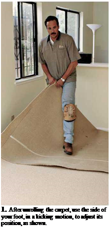
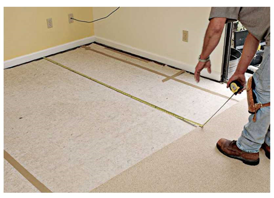
Carpet is heavy. So get help rolling it up and car­rying it. Unroll it in the room where you’ll install it. If you measured and cut properly, the edges of the carpet should curl up about 3 in. at the base of the walls. To adjust the carpet slightly once you’ve unrolled it, lift a corner about waist high. Then, as you stand with one foot on the carpet and one behind it, raise the foot that was on the carpet and, with the side of that foot, kick the carpet sharply. Note: By using the side of your foot, rather than your heel or toe, you’ll be less likely to stretch or tear the carpet.

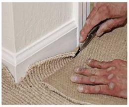
Many installers don’t cut fill pieces of carpet till they’ve positioned the drop piece and meas­ured from the drop piece to the wall. This allows them to double-check the size of the fill piece(s) needed. As with finish carpentry, "measure twice, cut once” is good advice, especially if the walls aren’t parallel. Once you’ve cut the fill pieces and positioned them next to the edge of the drop piece, go around the perimeter of the floor and loosely notch the carpet where it butts against door jambs and corners, so the carpet will lie flat—but don’t trim the carpet edges yet. First you need to join the carpet sections, using hot – melt seam tape.

image1043
image1041,image1042

HOT-MELT SEAMS

Join carpet seams before stretching and trim­ming the carpet. Correctly installed, hot-melt seams are strong enough to withstand stretching without separating.

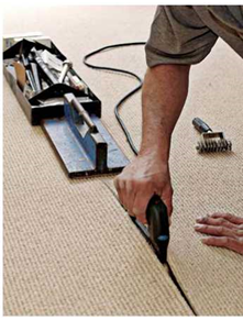
Use the knee-kicker to draw the seam edges together. After lining up the carpet sections, roll back one section slightly and slip a piece of hot-melt seam tape under the carpet edge so that the tape will run exactly down the middle of the seam. The tape’s adhesive-coated side should face
up. Plug in the seam iron, and let it heat up. Once it’s hot, place the iron on top of the seam tape at the start of the seam and let the carpet flop down on both sides, covering all but the handle of the iron. Most irons take about 30 seconds to heat the tape at a given point.

Once the adhesive has melted, move the iron farther along the tape. Then use a seam roller to embed the carpet backing in the melted adhesive. This operation isn’t difficult, but you must make sure that carpet edges butt together over the tape, rather than overlap each other. (Back-cutting the

Подпись:Подпись: llll

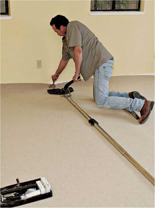
Подпись: 8. Once the hot-taped seams have cooled, they'll be strong enough to be stretched with a power stretcher and won't pull apart. When extended between opposite walls, the power stretcher's head typically moves the carpet about 2 in. as the lever is depressed.
image1044

carpets edges slightly with the row runner helps.) If it’s a cut-pile carpet, use a smooth roller to press the carpet backing into the seam tape; if it’s loop-pile carpet, use a star roller. After you roll a section of seam, weight it down as shown in the bottom right photo on p. 511. Continue along the seam—in roughly 12-in. increments—till the whole seam is bonded. Allow the adhesive to cool for 20 minutes to 30 minutes before stretching the carpet.

STEP3 Get to Know Electrical and Mechanical Systems

Houses are a lot like automobiles. Both work well if they’re cared for and maintained. In order to maintain your car, you need to know simple things, such as where and how to add oil or brake fluid, how to put air in the tires, and how to check the radiator. Sure, you could have a mechanic take care of this rou­tine maintenance, but it can quickly get expensive—and besides, it’s satisfying to understand the basics of your daily trans­portation. The same goes for a house. There’s no need to call a plumber every time you have a leaky faucet or an electrician every time a circuit breaker needs to be reset. Now that you’ve finished building an affordable house, you can maintain it affordablv with a little basic know-how.

Do electrical checks

For safety’s sake, one of the first things you should check is that all switch, outlet, door­bell, and exhaust fan covers are securely in place. As a homeowner, you should also know the location of the main electrical circuit box.

It contains wires leading to every part of the house and the circuit breakers, which are the

STEP3 Get to Know Electrical and Mechanical Systems

switches that control the electricity on indi­vidual circuits. Open the box door covering the circuit breakers and make sure the electri­cal contractor has labeled what each breaker controls. This circuit map should be on the inside of the door. You should be able to iden­tify the separate breakers for the stove, refrig­erator, and furnace, as well as lighting and receptacle circuits for different parts of the house. There will also be a large single breaker that completely shuts down the current throughout the house. With well-labeled breakers, you’ll be able to shut off power when you need to do wiring work on a specific switch or outlet.

Подпись: BE SAFE WHILE WIRING. Always shut off an electrical circuit before you work on any outlets or switches included in that circuit.Подпись: і ~ іПодпись: Helping HandПодпись: Buy plug-in protection. To protect small children from tampering with electrical receptacles and being harmed by an electrical shock, install protective plug-in devices in unused receptacles that are within a child's reach. Referred to as receptacle covers, these small plastic inserts can be removed easily by an adult who needs to use a covered receptacle.If an outlet doesn’t work, one of the first things to check is whether it’s a ground-fault circuit interrupter (GFCI) outlet. GFCI pro­tection is required for outdoor receptacles (outlets) and electrical outlets in the kitchen and bathroom—places where the presence of moisture might pose an electrical shock haz­ard. If overloading or an electrical short is detected, a GFCI circuit breaker will shut down at the main service panel, cutting off power to all outlets on the circuit. GFCI pro-

Подпись: DON'T FORGET THE SHUTOFF VALVES. Located beneath a sink, these valves allow you to shut off hot and cold water lines going to the faucet so that repairs can be made. [Photo ® Larry Haun.] Подпись: Helping HandПодпись: Store a wrench near the gas line's shutoff valve. Shutting off the main gas line quickly can save lives during an earthquake or a hurricane. Buy a wrench that fits the gas line shutoff valve, and store the wrench right next to the valve so that it's immediately accessible should an emer-gency occur.tection can also be provided by a GFCI recep­tacle that’s wired to other receptacles. Both GFCI devices have test and reset buttons. Find out which type of GFCI protection you have, where the devices are located, and which out­lets they control. By pressing the test and reset buttons, you’ll see how they work.
Know the water and gas lines

In the same way that there’s a main electrical shutoff switch in the electrical circuit box, there are also shutoff valves for the water and, in some places, the natural gas supplies that come into a home. Find out from your plumber and heating contractor where these valves arc, and label them clearly. Water and gas lines can break, and being able to shut off the flow of water or gas could mean the difference between a minor problem and a catastrophe.

Turning a valve on the gas meter with a crescent wrench can often shut it off. There is a shutoff’ valve on the main water pipe coming into the house. There are also localized shutoff valves under sinks and toilets and near washer – dryer units (see the photo above). These allow you to turn off the water to a particular appli­
ance so that you can fix a dripping faucet or make other repairs.

Be familiar with heating and air-conditioning components

The filter is an inexpensive but very important part of most forced-air heating systems. A central air-conditioning system also relies on a filter to trap dust and dirt that may otherwise be blown into living spaces when the system is operating. Make sure you know where these filters are located and how to change them. Replacing a furnace or central AC filter usually takes no more than a minute or two. Always have one or two new replacement filters on hand. Check your working filter against a new one, and replace the old filter once it’s discol­ored by trapped material. A well-functioning filter is good for your health and the health of your HVAC system.

STEP 4 Prepare for the Worst

Earthquakes, tornadoes, and hurricanes don’t come our way very often, but their brute force can be devastating—even fatal—if we’re not prepared. Disasters don’t just strike uother people.” Sometimes they happen to us.

1 remember inspecting a house in Califor­nia after a moderate earthquake. The house hadn’t collapsed, but the hot-water heater had been thrown 20 ft. out into the street. Other heavy appliances were scattered throughout the house. A good HVAC contractor knows which measures are required for securing equipment in areas where the risk of natural disasters are higher than normal. Steel strap­ping and other hold-down hardware are avail­able at most home centers. Check with your building department to see whether there are special requirements in your area for securing heaters and other appliances.

Croatia

In Croatia, the design of pavement structures primarily considers the traffic load. However, if the subgrade soil is frost susceptible and if the hydraulic conditions are unfavourable, the originally designedpavement structure shouldbe additionally tested to determine the impact of freezing. If there is a risk of freezing, certain technical measures have to be planned within the pavement structure or under it in order to avoid the risk of freezing or to significantly lower the impact of freezing. In Croatia the pavement testing concerning freezing is carried out in the following manner.

Based on the soil mechanics characteristics, the pavement materials and sub­grades are grouped into one of the following four groups according to their freezing susceptibility (in compliance with the national standard HRN U. E1. 012):

G1 – lightly susceptible (gravel) containing 3-10% of particles smaller than 0.02 mm.

G2 – lightly to moderately susceptible (gravel, sand) containing 10-20% of small particles.

G3 – moderately susceptible (gravel, sand, clay with PI higher than 12) con­taining over 20%, i. e. over 15% of particles smaller than 0.02 mm.

G4 – highly susceptible (dust, very fine dusty sand, clayey dust) containing over 15% of particles smaller than 0.02 mm.

According to the national standard HRN U. C4.016, it is established whether the hydrological circumstances are favourable or not.

400-500

300-400

Fig. A.1 Contour map with air freezing index (FI) for the territory of Croatia (Srsen et al. 2004). Reproduced by permission of the Croatian Association of Civil Engineers

Then the freezing depth is determined according to the national standard HRN U. B9. 012. It is required to determine the Freezing Index (FI) for that purpose. The FI value is taken from the freezing index contour map shown in Fig. A.1. That map is derived from an IGH study on Freezing Index determination for national roads in 2003, elaborated in cooperation with the Metrological and Hydrological Service. The study is based on the data on the highest and lowest air temperatures noted in 39 meteorological stations in Croatia in a period of 25 years (1976-2000) (Srsen et al. 2004).

The freezing depth under the pavement surface is read from a diagram based on FI and from the data on pavement thickness (designed or completed), its spatial mass and humidity and from data on the soil type under the pavement.

ROUGH-CUTTING CARPET

When rough-cutting carpet, it’s helpful if you can unroll it completely. If you don’t have enough room to do so indoors, unroll it on a clean, dry sidewalk or driveway. Sweep the area well before­hand, and make sure there are no oil stains on the ground.

Cut the carpet to the overall room dimensions on your sketch—plus the extra you included for seams and trimming along walls. At this stage, don’t cut out carpet jogs, such as along cabinets and around doorways, because you’ll cut those later, when the carpet is spread out in the floor you’re carpeting. Important: Before making any cuts, note the direction of the carpet pile, espe­cially if you have more than one piece of carpet­ing to cut.

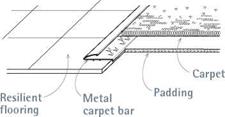
I Carpet Transitions

image1036

Edge tucked with stair tool

image1037

Wood flooring

Tackless strip

Tape the edge of the padding to keep it from riding up onto the tackless strips when stretching the carpet.

Transfer the room dimensions to the carpet. Use a felt-tip marker on the edge of the carpet to indicate the cut-line across its width, or use a utility knife to notch the carpet’s edges at each end of the proposed cut.

In general, cut loop-pile carpet from its pile side (its face), and cut cut-pile carpet from its backing side. To cut carpet with cut pile, flop the edge of the carpet over so its backing is up, and snap a chalkline between the two notches you made in the carpet’s edges. Cut along the chalk­line with a utility knife or a double-edged floor-

image1038

3. Before hot-taping carpet seams, help the carpet lie flat by notching carpet edges where they abut doorways, cabinets, and so on.

Подпись: 1. After unrolling the carpet, use the side of your foot, in a kicking motion, to adjust its position, as shown. image1040

ing knife, using a long metal straightedge to guide the blade. If the carpet is loop pile, cut it with the carpet facing up: Locate a pile row near the cut-line and run the blade of a large flat screwdriver between them, to separate the rows. Then push a row runner, as shown in the bottom photo on p. 509, steadily down the row to cut through the backing. The carpet pile will guide the cut.

CONSIDERATIONS IN LIFE CYCLE COST ANALYSIS

Life cycle cost (LCC) is the total cost of ownership of an item, computed over its useful life. To rationally compare the worth of alternative designs, or different ways to do a job (accomplish a function), an LCC analysis is made of each. For those who follow the

VE job plan, a life cycle cost analysis is very easy to perform because the total impact of each recommended VE alternative is an integral part of the total calculations. In reality, an LCC study uses VE techniques to identify all costs related to the subject (functional) area, and VE’s special contribution can be the selection of the best alternatives to be “life cycle-costed.”

LCC is the development of all significant costs of acquiring, owning, and using an item, a system, or a service over a specified length of time. LCC is a method used to compare and evaluate the total costs of competing solutions to satisfy identical functions based on the anticipated life of the facility or product to be acquired. In performing a value study, an LCC analysis is performed in the development phase of the value engineering job plan to determine the least costly alternative.

The value of an item includes not only consideration of what it costs to acquire it, but also the cost to use it or the cost of performance to the buyer for as long as the item is needed. The buyer, not the seller, pays the life cycle costs and therefore must determine value. One measure of value to the buyer is the calculated total cost of ownership.

Costs of repair, operations, preventive maintenance, logistic support, utilities, depreci­ation, and replacement, in addition to capital cost, all reflect on the total value of a product to a consumer. Calculation of the LCC for each alternative during performance of a value study is a way to judge whether product quality is being maintained in sufficient degree to prevent degradation of reliability, performance, and maintainability.

Life cycle cost analysis requires the knowledge of several economic concepts. One of these is the concept of equivalent costs in relation to time. Equivalent costs are typically developed by equating all costs to a common time baseline using interest rates to adjust for variable expenditure years. One must also hold the economic conditions constant while the cost consequences of each alternative are being developed. That is, the same economic factors are applied to each alternative using a uniform methodology.

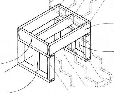
TOP OF CARRIAGE/FLOOR

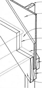
Hangerboard Supports Top of Stair

stud of

SuppORTiNG wALL


GypsuM wallboard

OR OTHER FiNiSH

wall


1x FiNiSH STRiNGER


FiNiSH RiSER TRiMS TO STRiNGER.


FiNiSH TREAD TRiMS TO STRiNGER.


BLOcKING BEHiND wALL FiNiSH


2x spacer nailed to studs

carriage nailed to spacer


TOP OF CARRIAGE/FLOORTOP OF CARRIAGE/FLOOR

Подпись: TOP OF CARRIAGE/FLOOR Wall Supports Top of Stair CARRIAGE FRAMING/SIDE WALL

Continuously Supported Stair

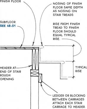
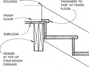
HEADER AT END OF STAIR

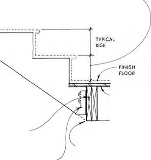
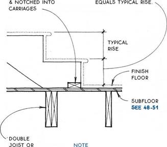
Подпись:Подпись: RISE FROM FINISH FLOOR TO FIRST TREAD EQuALS TYpicAL RISE.Подпись: SuBFLOOR SEE 48-51Подпись: LOCATE FLOOR HEADER TO INTERSECT WITH BOTTOM OF CARRIAGES.TOP OF CARRIAGE/FLOORПодпись: 2X THRUST BLOCK NAILED TO SUBFLOORПодпись: RiSE FROM FINISH FLOOR TO FIRST TREADTOP OF CARRIAGE/FLOORПодпись: BLOCKING TO SUPPORT STAIR Подпись: BLOCK BETWEEN FLOOR JOISTS IF BASE OF CARRIAGE DOES NOT FALL ON Tip OF JOIST.rough

OpENING FOR

multiple

FLIGHTS OF STAIRS

JOIST HANGER

TOP OF CARRIAGE/FLOOR TOP OF CARRIAGE/FLOOR

supports central carriage

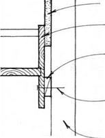
TOP OF CARRIAGE/FLOORПодпись: INTERIOR FINISH WALLTOP OF CARRIAGE/FLOORHOuSED STRINGER OF pREFABRicATED STAIR

5/8-IN. TO 1-IN.

shim accommodates thickness OF FINISH WALL

ATTAcH STRINGER WITH 16D NAILS THROuGH SHIMS INTO FRAMING

WALL FRAMING

Подпись: Section at Side WallSection at Top of Stair

PREFABRICATED STAIR

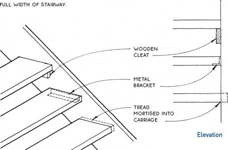
Подпись: ATTACHMENT OF TREADS TO CARRiAGE MAY BE WiTH:

WOODEN cLEATS

Подпись:TOP OF CARRIAGE/FLOORscrewed TO Structural cARRIAGE;

OR

metal bracket let into

END Of TREAD SO THAT

bracket is concealed

FROM ABOvE (AND DOES NOT pROJEcT BELOW);

OR

MORTISED TREAD, WHicH

provides concealed connection FOR AppEARANcE; ScREW TREADS THROuGH

carriage or glue &

TOENAIL FROM underside INTO carriage.

Finish landings must be at least as deep as the stairway is wide (automatic in the case of an L-shaped stair). Set the landing height so that the finish-floor level corre­sponds to the rise of the stair.

Подпись:Подпись: / .«■*;.< /Подпись: FRAME LANDiNG AS A FLOOR SEE 32 —Подпись: EXTEND LANDING UNDER CARRIAGE OF UPPER FLIGHT OF STAIRS.Подпись: ATTACH CARRIAGE OF LOWER FLIGHT OF STAIRS TO SIDE OF LANDiNG. SEE 212A, В & cTOP OF CARRIAGE/FLOORSUPPORT LANDiNG ON STUD WALLS.

COST MODEL

A cost model is a diagrammatic form of a cost estimate. It is used as a tool in the VE process to provide increased visibility of the cost of the various elements of a system or an item, to aid in identifying the item’s subelements most suitable for cost reduction attention, and to establish cost targets for comparison of alternative approaches. It also helps define the worth of an element.

A cost model is an expression of the cost distribution associated with a specific item, product, or system. In industry, it is often referred to as a work breakdown structure. A cost model is developed by first identifying assembly, subassembly, and major compo­nent elements or centers of work. From this, the model can be expanded to include a parts breakdown at more minute levels, as necessary. Next, the costs are developed (actual, estimated, or budgeted) for each of the above categories. These become the cost elements of the model and can be viewed as the cost building blocks of cost buildup from successive levels.

Shown in Fig. 10.3 are five common categories of cost for a government construction program. Some additional items that should be considered, particularly for a commercial project, include cost of land, financing charges, building permits, and taxes.

10.5 WORTH MODEL

The same form of model used to distribute cost of a system can be used to allocate worth. The cost model and the worth model should be identical in format. The procedures to follow in creating a worth model are as follows:

1. First, the VE team determines the necessary functions to be performed by each ele­ment of work at the lowest level of activity of the cost model.

2. The worth of each of these functions is determined as explained in the job plan.

Partition

drawings

Design changes

FIGURE 10.3 Cost model for construction program.

3. The worth of all functions for each cost element is totaled and becomes the worth for that element.

4. The sum of the worth of all cost elements becomes the worth of the corresponding cost element at the next higher level.

Thus, the VE team develops the minimum costs it believes are possible for each block of the cost model. The result is a cost model representing minimum costs. These costs become targets to be compared with costs as reflected by the best estimates available. Cost blocks having the greatest differences between target and estimated costs are then selected for VE study.

(H. G. Tufty, Compendium on Value Engineering, Indo-American Society, Bombay, 1989.)