Category HIGHWAY ENGINEERING HANDBOOK

Prestressed-Concrete Box-Beam Bridges

The span range of a shallow bridge may be extended beyond the limits of a slab bridge by using precast prestressed-concrete box beams as illustrated in Fig. 4.6. The beams are prefabricated off-site. They are rectangular and, except for very shallow beams [12 in (305 mm)], which may be solid, have from one to three rectangular or circular voids. The void forms are either waterproofed cardboard or solid polystyrene foam and are left in the beams. Void drains must be provided to prevent entrapment of water. Prestressing strands are located on the bottom and in the sidewalls of the box, and may include debonded or deflected strands. The selection depends upon owner preference or, where the designer and owner allow the option, fabricator preference.

Wearing surface

This type of bridge can be constructed using adjacent beams or spread beams. In adjacent box-beam construction, prefabricated box beams are placed side by side, abutting each other. The box beams are connected by transverse tie rods or posttensioned tendons, or by welded connection of tie plates to plates embedded in the tops of the beams. Shear keys between beams are grouted. The combination of transverse connection and grouted shear keys is intended to make the beams act together as a unit and prevent relative movement and cracking at the longitudinal joints. This type of bridge can be erected quickly, and temporary traffic can be maintained on partially completed portions of the bridge. These features have made this a popular type of bridge, despite at least one shortcoming discussed below, and sometimes cause it to be selected over a com­petitive type when both types are viable candidates for a bridge of a given span length.

For low-traffic-count roads, the tops of the beams may constitute the riding surface, but on most bridges a topping will be used. This may be a composite concrete slab, which adds to the strength of the bridge, or an asphalt concrete overlay, which is used to smooth out any irregularities between beams, to compensate for difference between roadway profile and final camber of the beams, and sometimes to maintain continuity of pavement type when the adjacent roadway is asphalt concrete. A waterproofing mem­brane should be used with this type of construction, with special attention to the joints.

The elimination of movement at the longitudinal joints and the maintenance of a water­proof condition has not always been achieved, even when a composite concrete slab has been used. Leakage of roadway drainage containing deicing salt through longitudinal joints has sometimes resulted in corrosion of the prestressing strands. In some cases, wires have broken.

In spread-box construction, the beams are spaced apart, and a reinforced-concrete slab is constructed on top. The slab between the beams is formed, and stay-in-place steel forms are frequently used. This has been an economical type of construction in Pennsylvania. In bridges with end spans shorter than interior spans, the beams can be the same depth for aesthetic reasons, with the spacing between beams varied to meet structural requirements. However, diagonal and vertical cracks have been observed in the sidewalls of spread-box beams near supports in sharply skewed bridges. The fine diagonal cracks were most evident on the acute sides of the box beams.

Reinforced-Concrete Flat-Slab Bridge

For short simple spans (up to 30 ft or 9.1 m) and for somewhat longer continuous spans (interior spans up to 55 ft or 16.8 m), reinforced-concrete flat slabs provide a minimum – depth bridge. Figure 4.5 shows a schematic of this bridge type. At a slab depth of about 2 ft (610 mm), the slab begins to become uneconomical, with too much of the section required to support itself.

Falsework is required to construct the slab. Where space is available beneath the struc­ture, scaffolding may be used. If the bridge is over a stream, or over a highway or railroad

TABLE 4.2 Approximate Maximum Span for Various Types of Bridges

Подпись: Approximate

maximum

Type span, ft (m)

Reinforced-concrete flat slab, continuous 55 (17)

Composite steel beam (36-in series), simple 100 (30)

Precast prestressed-concrete voided box beam 120 (37)

Precast prestressed-concrete beams (bulb-tee), simple 120 (37)

Composite steel beam (36-in series), continuous 125 (38)

Precast prestressed-concrete beams (bulb-tee), made-continuous 140 (43)

Composite steel plate girder, simple 230 (70)

Precast prestressed-concrete beams (bulb-tee) spliced 250 (76)

Cast-in-place (on falsework) posttensioned-concrete box girder, continuous 300 (91)

Precast posttensioned segmental concrete box girder, continuous, 400 (122)

balanced cantilever

Composite steel plate girder, continuous, parallel flange 460 (140)

Composite steel plate girder, continuous, haunched 540 (165)

Cast-in-place posttensioned segmental concrete box girder, continuous, 850 (259)

balanced cantilever

Steel arch (New River Gorge, Fayetteville, West Virginia, U. S.A.)[3] [4] 1700 (518)

Steel cantilever truss (Pont de Quebec, Canada)* 1800 (549)

Steel cable-stayed (Stonecutters, Hong Kong)* 3340 (1018)

Suspension (Akashi Kaiko, Japan)* 6529 (1990)

where traffic must be maintained, the falsework must include support beams to span over the feature crossed. In that case, camber should be built into the falsework to compensate for its deflection. Also, the falsework must provide for the vertical geometry of the bridge and for deflection of the slab after removal of the falsework.

Longer continuous-slab spans can be constructed if the slab is haunched, that is, made deeper over the piers or bents. However, the cost and difficulty of constructing the forms, and bending and placing the longitudinal reinforcing bars, often negates the advantage of haunched construction.

Another type of construction that can be used to extend the span capability of slab bridges is voided construction. Voids, similar to those used to fabricate prestressed- concrete box beams, are used to replace the relatively ineffective concrete at mid-depth of the slab, thereby reducing the weight of the slab. However, where this type of construc­tion has been used, it has generally been found to be more expensive than competitive types of bridges. A principal reason is the cost of providing adequate hold-down devices to prevent the voids from floating when the concrete is placed.

For balanced design of continuous-slab bridges, the usual rule that the end span should be shorter than the adjacent interior span may not apply. In the design of a three – span continuous flat-slab bridge with three equal spans of 30 ft (9.1 m), considering an HS 25 live load (a load 25 percent greater than HS 20) and the AASHTO Alternate Military Loading, a good balance resulted between maximum positive and negative moments using equal span lengths.

CHARACTERISTICS AND SELECTION OF BRIDGE TYPES

The type of bridge and the span layouts are interdependent. Bridge type cannot be selected without regard to the length of spans, the ratio of adjacent span lengths, and whether spans are to be made continuous.

Table 4.2 lists common types of bridges and the maximum span lengths below which they may be an economical choice. The maximum spans tabulated are approximate, and are presented as a guide only. They are subject to increase as technology advances. Similarly, increases in specified live load may tend to reduce the maximum span. The economic competitiveness of a particular bridge type varies with regional availability and workload of fabricators and specialty contractors, yearly fluctuations of labor and material costs, and other factors. Thus, it is usually desirable to seek and permit bids on alternative bridge types.

Characteristics of some of the more common bridge types for short and intermediate spans and considerations in their selection are discussed in the following articles.

CONTINUITY AND JOINTLESS BRIDGES

Where possible, bridges should be made continuous. Continuous spans are less prone to catastrophic collapse from loss of substructure support due to stream erosion, earth­quake, or vehicle or vessel collision. Bridges with multiple simple spans must have two lines of bearings and an expansion joint at each intermediate support. Two lines of bearings, each having the required capacity for the end of a simple span, will almost certainly be more expensive than the single line of bearings required for con­tinuous spans. Expansion joints are expensive and in most geographic locations should be sealed against storm drainage and intrusion of debris, which further increases their cost. (Even the manufacturers of sealed expansion joints agree that the best joint is no joint.) Aesthetically, continuous bridges are generally superior, especially if constant depth is maintained, and do not require the cosmetic plates or other devices that have sometimes been used to conceal the gaps between simple spans.

Continuous bridges are generally more economical than simple-span bridges because of the reduction of mid-span moments. Most bridges can be designed continuous for live load, and some bridges may be designed continuous for dead load as well. In the case of precast prestressed-concrete bridges, it is generally more convenient and economical to place the deck slab concrete while the beams are supported on their bearings, without temporary intermediate shoring, so that the beams are not continuous until the deck slab has acquired its strength and top longitudinal reinforcing bars are present in the compos­ite section over the piers to resist negative moment. Therefore, these bridges are designed continuous for live load and for superimposed dead loads (loads above the deck slab) only. Note that this type of construction unavoidably requires two lines of bearings at intermediate supports because practical prestressed-concrete design and construction require that the spans be simple initially. This is called “made-continuous” construction.

There are situations where simple spans are preferable. Examples include situations where adjacent spans are unavoidably different in length and depth, or where adjacent spans have widely different geometrics with beam layouts that do not lend themselves to continuity, such as varying beam spacing or splayed framing. Simple spans may also be preferable where the bridge is part of a facility, such as an interchange, where stage construction will require future removal or addition of one or more spans. Simple spans are also desirable where differential substructure settlement is anticipated.

Expansion Joint Sealers

Several types of expansion joint-sealing devices are available. Properly sized and installed, they can greatly reduce, if not eliminate, drainage through the joint. Some of the available types are

• Polymer-modified asphalt

• Compression seal

• Slab-type seal

• Strip seal

• Modular seal

Polymer-Modified Asphalt. For resurfacing projects where an asphalt concrete overlay or a portland cement concrete overlay is placed on an existing bridge deck, the approach slab is also overlaid, and the joint movement is moderate (no more than 1.5 in or 38 mm), an expansion joint seal using a poured liquid joint sealer and “armor” of polymer-modified asphalt concrete (elastomeric concrete) can be used. Construction is simple and requires only a minimum of removal of the existing structure, if any. The elastomeric concrete will bond to steel, concrete, or asphalt concrete, and also develop a tenacious bond with the liquid joint sealer, which is poured over backer rod installed between formed vertical faces of the elastomeric concrete. Figure 4.1 illustrates this seal.

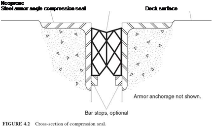
Compression Seal. The compression seal (Fig. 4.2) is a rectangular elastomeric tube that has internal webbing and is manufactured by extrusion. It is installed between formed or sawn faces of concrete, or, more commonly in bridges, between steel armor. A lubricant/adhesive is used to facilitate installation and prevent displacement in service.

Cold-applied pourable self-leveling joint sealer

Polymer-modified asphalt

Existing deck surface,

(elastomeric) concrete

asphalt or concrete

Backer rod

FIGURE 4.1 Cross-section of polymer-modified asphalt concrete joint seal.

Подпись: Neoprene Steel armor angle compression seal Deck surface

Compression seals can be of the high-compression type, which relies more on internal compression than on the adhesive to stay in place, or the low-compression type, which relies more on the adhesive. The high-compression type is more subject to loss of tight fit due to compression decay with age, and so is less desirable. Catalogs will not describe the seals in this manner, but manufacturers’ representatives will know. A clue to the type of seal is the number of internal webs, which is greater for the high-compression type.

Compression seals are available for joint widths up to 5 in (127 mm), but some agencies impose a 4-in (102-mm) limit. Some skew can be accommodated by using a larger seal than would be required for an unskewed joint. A maximum allowable skew of 15° (with respect to a line normal to the bridge centerline) is imposed by one state. Seals should be one piece for the entire length of the joint.

A variation of the compression seal is a proprietary seal that has no internal webbing. It is installed in the joint by air inflation, which presses the sides against the supporting surfaces, onto which an epoxy adhesive has been applied. The air pressure is released after an adequate curing period, and the adhesive is relied upon to maintain the seal in position.

Slab-Type Seal. The slab-type sealing device consists of an elastomer and internal steel plates that combine to provide a surface that bridges over the joint opening and supports traffic loads. There are notches in the slab that, along with the elasticity of the elastomer, permit it to change length. The sides of the slab are supported on horizontal steel or concrete surfaces, and a bedding adhesive is applied before the slab is fastened down. The slab is fastened to the bridge by closely spaced bolts.

A primary disadvantage of the slab-type seal is that large stresses are induced in the slab by temperature changes, which, along with pounding by traffic, tend to break it loose. Some users of slab-type seals have had satisfactory experience with them, but most users have changed to other types of seals.

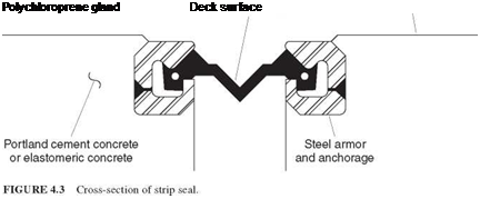
Strip Seal. The strip seal (Fig. 4.3) is an elastomeric extrusion, called a gland, that spans between supporting steel armor. It is anchored by enlargements on the ends of the glands, which are inserted into grooves in the armor. The gland is generally only one layer thick, but some strip seals have two layers, the lower of which should act as a back­up if the top layer is punctured. A lubricant/adhesive is used to facilitate installation. Like

Подпись: Polychloroprene gland Deck surface

the compression seal, the gland should not be spliced. Special tools should be used to install the gland, and the gland should not be stretched during installation. Left by them­selves, contractors may try to use inappropriate tools and brute force to install the gland.

Strip seals can accommodate skew somewhat better than compression seals and are favored by agencies for joint openings larger than can be accommodated by compres­sion seals.

Подпись:
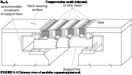
Modular Seal. At the ends of long bridges, or the ends of individual units of long bridges, the joint movement may be greater than can be accommodated by a single joint seal of the types described above. In this case a finger joint with an elastomeric trough may be used, or a modular joint can be provided. The modular joint consists of multiple compression seals or strip seals separated by steel or aluminum structural members, which are in turn supported by bars that span transversely to the joint, parallel to the centerline of the roadway. Figure 4.4 illustrates this type of seal. The support mechanisms can become quite elaborate, with sliding bearings and components to ensure that uniform spacing between longitudinal seal elements is maintained. The designs must provide for joint rotation as well as translation. It is also important that the design of these joints allows for replacement of components.

The fact that many specifiers of sealed expansion joints do not expect them to be, or remain, watertight throughout their life is indicated by the practice recommended for weathering steel bridges (see Art. 4.13). That recommendation is that the steel be painted at the joints, and is applicable to sealed and unsealed joints alike.

Failure of an expansion joint can occur in the sealing mechanism itself, but in the past, failures have occurred as frequently in the anchorages. Some causes of anchorage failure have been

• Inadequate consolidation of concrete below wide legs of armor angles

• Too small or too widely spaced welded stud anchors

• Vulnerability to snowplow damage because the sealing device was not recessed below the wearing surface

• Pressure exerted during thermal changes by overlapping steel angles because the joint design did not properly accommodate longitudinal grade

• Material used to bed or anchor the joint sealing device that was not shrinkage-resistant and broke under traffic

Expansion Joints

Bridge roadway expansion joints are provided to accommodate the thermal changes in the superstructure, and, in the case of prestressed-concrete bridges, to accommodate creep shortening of the superstructure as well. They are required at abutments that are restrained against longitudinal movement and at the end of supported superstructures free to translate due to provision of expansion bearings. In some long-span steel bridges, expansion joints and expansion bearings must also accommodate change of length of span due to live load deflections. Expansion joints are not required in short bridges where movement is small— for example, in steel bridges with span less than 50 ft (15 m)—or in longer bridges where the superstructure is fixed to the abutment (jointless bridges or integral construction). For these longer bridges, designs that eliminate or minimize bridge expansion joints, without introducing problems in the approach roadway or causing distress in the superstructure or substructure, are favored. (See Arts. 4.15 and 4.16.7.)

Expansion joints, or, more accurately, rotation joints, are also provided where the deck is made discontinuous, or a hinge is provided, in anticipation of settlement of the end of a span.

Where expansion joints are required, they should be sized to accommodate the anticipated movement with a liberal allowance. A joint-sealing device such as a strip seal can be destroyed by one occurrence of a record cold period. For deep simple-span girders, the joint movement due to live load rotation of the end of the span should be included. Specifications for installation of joints should take setting temperature into account. A table giving required joint opening dimensions for different ambient tem­peratures is preferred over an equation for adjustment of a fixed dimension that is applicable to a given temperature. In areas where roadway deicing salts are not applied, it may not be necessary to seal expansion joints. Even in this case, though, sealed expansion joints will prevent intrusion of foreign objects, which can damage the bridge by causing excessive local pressure, and will prevent accumulation of debris on bridge seats.

Large-capacity open expansion joints can be fabricated using steel plates with meshed fingers, the so-called finger joint. Finger joints have served well for many years on many bridges. The plates used in these joints must be thick to withstand the direct cantilever wheel loading to which the fingers are subjected. The two halves of finger joints are massive steel fabrications, but they can be gas-cut with accurate dimensional control. In snowplow areas, where the ends of the fingers may be snagged by the plow blade, the use of a finger joint should be avoided, or the ends of the fingers should be rounded downward. In areas where joints should be sealed, the finger joint surface may be left open, but an elastomeric trough should be installed beneath the joint.

Bicycles should not be permitted on bridges with finger joints, because the wheels can drop into the space between fingers, causing injury to the rider. Conversely, open finger joints should not be used on bridges on which bicycles are permitted.

In areas of salt application, expansion joints must be sealed. Northern states have incurred tremendous cost to repair damage to superstructures and substructures in the form of steel corrosion, prestressed-concrete beam deterioration, and concrete spalling due to salt drainage through open or inadequately sealed expansion joints.

DEFLECTION AND EXPANSION JOINTS

Joints in bridges fall into two categories: deflection joints and expansion joints.

4.14.1 Deflection Joints

Contrary to what the name implies, deflection joints, when placed in concrete barriers and parapets, are used primarily to minimize the vertical shrinkage cracking that would otherwise occur in long, unjointed panels. Some states permit a longitudinal spacing of joints as great as 30 ft (9.1 m) in simple spans. Over piers of continuous bridges, the spacing is generally less, 7.5 ft (2.3 m) or closer. Preformed joint filler is used to form the joints and is left in place. Sometimes the placement of parapet concrete is required to be done in two stages, with placement of alternate panels only in the first stage, to facilitate placement of the joint filler.

When barriers are permitted to be slipformed, the deflection joints are sawn an inch or so deep on the periphery of the barrier, and then caulked with a joint sealer. In this case, the steel is not made discontinuous at the joints. Slipforming is a much faster way of constructing barriers, but the finished appearance, especially the straightness of the top, is sometimes rather crude compared with conventionally formed barriers.

Deflection joints can extend full depth of the barrier or parapet, or through only the top portion. Deflection joints in the New Jersey safety-shape barriers, when the concrete is placed in forms, are sometimes placed only above the curb portion of the barrier. In this case, the longitudinal reinforcing steel is continuous in the curb, but discontinuous at the joints above the curb. This usually results in reflection cracks developing in the curb below the joints.

It is also common, in spite of the joints, to see one or more vertical cracks between the joints in long panels. These cracks may be aggravated by bridge deflection but are caused primarily by shrinkage. The development of these cracks illustrates a rule of thumb applied to slabs on grade, that there will be a tendency to crack if the slab is longer than twice its width. However, the likelihood of ultimate damage to the bridge resulting from these unwanted cracks is small, and so the cost to provide more closely spaced joints is not justified.

Deflection joints are also used in the deck slab at piers or over transverse floor beams where the slab is not continuous (and sometimes when it is continuous), and at abutments where the bridge slab abuts the approach slab. Since the amount of movement is small, due only to rotation, the joint can be sealed with a small compression seal or with liquid joint sealer.

WEATHERING STEEL

The cost of initial painting and periodic repainting of structural steel bridges can often be eliminated by the use of bare weathering steel. From an economic standpoint, the use of multicoat high-technology paint systems should be reserved to those bridges that are not suitable candidates for weathering steel.

To ensure successful long-term performance, the Federal Highway Administration

(FHWA) has published “Guidelines for the Use of Unpainted Weathering Steel.”

Principal considerations are as follows:

• Consider with caution use in marine coastal areas; in areas of frequent high rainfall, high humidity, or persistent fog or condensing conditions; at grade separations in “tunnel-like” conditions; and at low-level water crossings. (Some states such as New Jersey require painting of weathering steel girders if within 15 ft (4.6 m) of salt water.)

• Eliminate expansion joints where possible.

• Use a trough under open expansion joints.

• Paint all steel within a distance of US times the depth of girders from bridge joints.

• Seal box members where possible or provide weep holes to allow proper drainage and circulation of air.

• Seal overlapping surfaces exposed to water to prevent capillary penetration action.

• Implement maintenance and inspection procedures designed to detect and minimize corrosion.

• Divert roadway drainage away from the bridge.

• Clean troughs, reseal deck joints, and periodically clean and—when needed— repaint all steel in the vicinity of joints.

• Regularly remove all dirt, debris, and other deposits that trap moisture.

• Regularly remove all vegetation that can prevent natural drying of wet steel surfaces.

CORROSION PROTECTION OF NEW STEEL BRIDGES

The application of protective coatings to steel bridges, and the maintenance reapplication of coatings, is costly and so alternatives to the use of coated steel should be sought. Where appropriate, unpainted weathering steel should be used instead (see Art. 4.13). If a coated bridge is still the best candidate for the particular location, a long-lasting coating system should be applied.

Modern Paint Systems. The development of high-performance paint systems for new bridges has resulted mostly in two – or three-coat systems involving combinations of various materials including organic and inorganic zinc, epoxy, and urethane. The prime coats of these systems require cleaning the steel to a white or near white condition, which is an expensive operation even when done conveniently in a steel-fabricating plant. The application of subsequent coats, especially field coats, is labor-intensive. Despite these factors, these new systems can provide acceptably economical protection.

Water-Based Paint. The most recent emphasis in the development of paint systems has been on water-based paints. Because they do not contain volatile organic com­pounds, water-based paints can easily conform to the environmental restrictions placed on the levels of those compounds emitted during the painting process. Evaluation of this system and other systems continues. At this time, one can say that there is no one single paint system that is the best and most economical for all exposures. If a department of transportation or another agency representing an area with diverse geography, climate, or industrial development dictates a single-paint system for all parts of that area, it is likely that some of the bridges will be overprotected and some underprotected.

Galvanizing. Depending on local availability of galvanizing facilities of adequate size, steel members of limited length can be hot-dip galvanized. In addition to the deposition of zinc, the galvanizing process results in a change in chemistry of the surface of the steel, where an alloy is created, so that a degree of protection remains after the zinc coating is gone. The different stages of loss of coating and rusting that will eventually occur on galva­nized steel can be seen on exposed highway hardware such as galvanized steel roadside barriers, luminaire supports, and traffic sign and signal supports. Since these structures are more exposed to salt spray than a bridge superstructure may be, unless the bridge is a grade-separation structure, the longevity of the protection may be expected to be greater on a bridge.

Fusion-Bonded Coating. The coating of large structural members by fusion bonding with epoxy or other powders is now feasible in at least one coating plant, but this method of coating has not been used extensively for bridges. It is frequently used for pipe piles.

Metallizing. Another method of coating steel, which has been used on small components of new bridges, such as bearing plates, and on a few existing bridges, is application of a metallic coating by the flame spray method, or “metallizing.” The existing steel is first prepared to a near white condition. Then a continuously fed wire is vaporized in a flame and sprayed onto the surface of the steel. Although results have been satisfactory, the cost on complete bridges has been extremely high compared with other methods of coating.

Selection of Protection System. Environmental conditions and owners’ experience may dictate the selection of a corrosion protection system. Where acceptable life of protection can be expected from galvanizing, painting, or use of unpainted weathering steel, the selection may be based on initial or life-cycle cost. Alternative bids should be encouraged.

SELECTION OF MATERIALS FOR MAIN SUPERSTRUCTURE MEMBERS

For the primary superstructure members of a bridge (not including the deck), concrete (reinforced and prestressed) and structural steel are the principal candidates. Concrete and steel both have desirable attributes and shortcomings as bridge materials. In general, bridges of both materials can be designed, constructed, and maintained to ensure long life.

Claims of both steel and concrete industry associations, including references to national bridge inventory data used to support contentions of superiority of one material over the other, must be critically considered. One can find examples of both concrete and steel bridges that are old and in good condition, and conversely, relatively new and in poor condition. The trade associations do a service in countering each other’s claims.

Some advantages of concrete bridges are

• They do not require painting.

• They do not rust (but are susceptible to rebar corrosion).

• They can be formed to the desired shape (if of reinforced concrete).

• If of prestressed concrete, they may be fabricated more quickly than steel, although in some emergencies steel replacement structures have been fabricated and erected as quickly as prestressed members.

• They are not susceptible to fatigue failure (to date).

Some advantages of steel bridges are

• Lighter weight permits smaller cranes for erection.

• Lighter weight permits reduction of substructure size, number of piles, etc.

• They are more readily dismantled and reused at the same or another site.

• Use of conventional erection and construction techniques may avoid construction cost overruns and litigation sometimes experienced with segmental concrete.

• Attachments to bridge are readily made by bolting or welding.

• Components are accessible and visible for inspection.

• Members damaged by vehicular collision may be more easily repaired than con­crete members.

For short – to medium-span bridges, the selection of material will depend on which bridge type and material are the most economical for the particular site. This may be known by experience with bids received over a period of time, or can be determined by taking alternative bids on projects.

Long-span bridges are often designed in both steel and concrete, or in different framing systems of the same material, so that contractors bidding on both sets of plans can make the determination of which is less costly. An increasingly common practice for bridges of all sizes is to allow the contractor to submit alternative designs, which must be designed by professional engineers and conform to the requirements of the owner.