Category HIGHWAY ENGINEERING HANDBOOK

AESTHETIC CONSIDERATIONS

While highway bridges are utilitarian structures, they are visible to the public and therefore should be pleasing to the eye. At the outset of design, one should be conscious of the aesthetic qualities of the structure, lest one end the project saying (after Shelley), “Look on my works, ye Mighty, and despair!”

Some basic guidelines that were adopted by the Ohio Department of Transportation (DOT), Bureau of Bridges and Structural Design, and are included in its Bridge Design Manual illustrate the commonsense approach that can be taken to apply this consciousness:

Aesthetics. Each structure should be evaluated for aesthetics. Normally it is not practical to pro­vide cost premium aesthetic treatments without a specific demand; however, careful attention to the details of the structure lines and forms will generally result in a pleasing structure appearance.

Aesthetic bridge guidelines containing useful and practical information on how aesthetic quality can be recognized and incorporated in bridge design at minimal cost are as follows:

a. Avoid mixing structural elements, for example concrete slab and steel beam super­structures or cap and column piers with wall type piers.

b. In general, continuous superstructures shall be provided for multiple span bridges. Where intermediate joints cannot be avoided, the depth of spans adjacent to the joints preferably should be the same. Avoid the use of very slender superstructures over massive piers.

c. Abrupt changes in beam depth should be avoided where possible. Whenever sudden changes in the depth of the beams in adjacent spans are required, care should be taken in the development of details at the pier.

d. The lines of the structure should be simple and without excessive curves and abrupt changes.

e. All structures should blend in with their surroundings.

One of the most significant design factors contributing to the aesthetic quality of the structure is unity, consistency, or continuity. These qualities will give the structure an appearance of a design process that was carefully thought out.

The aesthetics of the structure can generally be accomplished within the guidelines of design requiring only minimum special designs and minor project cost increase. As special situations arise preliminary concepts and details should be developed and coordinated with the Bureau of Bridges and Structural Design.

Some states have adopted, in principle if not in writing, a similar philosophy in regard to aesthetics of their bridges. California, for example, is known and admired for applying some degree of architectural attention to all of its bridges. Some agencies, however, seem to neglect aesthetics, particularly in regard to the very visible piers of grade-separation bridges. Here the primary objectives seem to be standardization of shape to facilitate computer design, and emphasis on straight, flat lines to obtain minimum cost of forming. These objectives are achieved at a price—ungraceful substructures not in keeping with the lines of the superstructure.

CLIENT-CONSULTANT RELATIONSHIP

State departments of transportation, bridge and turnpike authorities, and other agencies often require the services of a consulting engineering firm. This may be because the agency chooses not to maintain an engineering staff of its own, because its workload is greater than its staff can handle, or because expertise in special kinds of bridges is needed. Consultants can fill these needs.

Where only routine types of bridges are involved and the agency has an engineer­ing staff, the best that a consultant can be expected to do, usually, is only as good a job as the agency’s engineers can do. The agency’s staff may include veteran engi­neers who have become extremely proficient in design of routine and not so routine bridges, and who also know exactly how to prepare plans in the proper format and sheet sequence preferred by the agency, as well as how to use exact pay item

descriptions and to refer to pertinent proposal notes and special provisions. A consul­tant, in this instance, is like a temporary employee who knows the basics but needs to be trained in local procedures.

When a consultant serves a client for many years, however, that consultant can become as proficient as the agency’s staff. Long-term contracts for continuing or on-call services eliminate the need to train a new consultant. However, they can be seen as showing favoritism in an environment where other consultants expect an opportunity to compete for contracts. For this reason, and because a long-term contract may allow a consultant to become complacent, the client may limit the term of the contract and, upon expiration, issue a request for proposals (RFP) to perform the services. The original con­tract holder may or may not be eligible to respond to this RFP, at the agency’s discretion.

In other instances, agencies may hire consultants as program managers. In these cases, the consultant manages designated design and construction contracts for the agency, providing administration, technical review, and construction inspection services.

Consultant’s Responsibilities. To serve the client in a professional and efficient manner, the consultant should

• Deliver the product promised in the contract scope of services

• Deliver the product on time

• Conform to accepted codes and standards

• Develop economical designs

• Use time-tested materials, avoiding purely experimental materials and systems

• Confirm in writing to the client any verbal understandings

• Keep the client informed of project status

• Avoid issues that could involve the client in litigation

• Not make statements to the public or to the media without the client’s knowledge and authorization

Client’s Responsibilities. Just as the consultant has a responsibility to the client, the client has a responsibility to the consultant. Responsibilities include

• Executing a contract with the consultant that includes adequate hours to perform the work, recognizing any unique requirements, and not applying standard allowances for nonstandard work.

• Performing reviews in a timely manner.

• Performing reviews either concurrently or sequentially, but not expecting the consultant to make changes required by one branch of the client’s office only to be subsequently countermanded by another branch. In other words, the client should transmit con­solidated review comments.

• Not interrupting the work unless absolutely necessary.

• Paying invoices in a timely manner. Contracts with subconsultants often stipulate that the subconsultant’s invoices will not be paid until payment is received from the prime consultant’s client, so a delay in payment from the client results in delay of payment to the subconsultant.

• Being frank with the consultant about any dissatisfaction the client may have with the consultant’s performance so that corrective action can be taken immediately.

If the client and consultant meet their respective responsibilities, the relationship will be a partnership that benefits both parties.

BRIDGE ENGINEERING

Walter J. Jestings, PE.

Formerly, Bridge Engineer
Parsons Brinckerhoff, Quade & Douglas, Inc.
Atlanta, Georgia

Mahir Sen, P. E.

Professional Associate
PB Americas, Inc.

Newark, New Jersey

This chapter is directed at practical issues of importance in the design and rehabilita­tion of traditional bridge types for short and medium spans. Subjects addressed include characteristics of various bridge types, considerations in their selection, and suggestions for economical design; materials for bridges and bridge decks; bridge deck design, construction, and maintenance; deflection and expansion joints; and bridge bearings. The issues are addressed from a general viewpoint, with the emphasis on what is generally done and why. Detailed design methods are available in other publications. (See R. L. Brockenbrough and F. S. Merritt, Structural Steel Designer’s Handbook, McGraw-Hill, and E. H. Gaylord and C. N. Gaylord, Structural Engineering Handbook, McGraw-Hill.)

LIFE CYCLE COST ANALYSIS OF PAVEMENTS

It is seldom readily apparent which is the most economical rehabilitation method for a particular pavement. Each rehabilitation strategy has unique initial construction costs, performance expectations, and future maintenance needs. What is most economical for one pavement may not be for another. Local costs may differ from one location to another, and material performance expectations may be different from region to region. The only rational way to compare one rehabilitation strategy and another is to perform an economic analysis of the alternative strategies. The method used for such a study is the life cycle cost analysis (see Chap. 10).

It is not good practice to compare a minor pavement rehabilitation strategy and a complete pavement replacement strategy. Even when comparing a new rigid pave­ment and a new flexible pavement, difficult choices must be made concerning the expected performance of each pavement type. Table 3.29 shows a hypothetical example of life cycle cost analysis assuming a 35-year performance period for both alternatives with no salvage values at the end of the period. It is not the intent to show that one pavement type has an economical advantage over another, as many hypothetical assumptions were made in the example. The intent is to indicate the level of information needed to make a life cycle cost analysis, and the information an analysis presents.

Probably the most important consideration in a life cycle cost analysis is the selec­tion of the discount rate used to evaluate the time value of money. It is sometimes defined as the difference between the market interest rate and the rate of inflation. (Article 10.8.2 provides further discussion on this subject.) Because costs are incurred at different times over the life of a pavement, the discount rate is used to convert these costs occurring at different times to equivalent costs in present dollars. In the example

Length: 3.16 mi (5.08 km) Lane number: 5 Lane width: 12 ft (3.66 m) All Lane widths vary; average width of roadway

Dimension,

Item in

sections in curb—no shoulders ■ = 60 ft (18.3 m)

Quantity analysis

Cost analysis

Unit

ALT1

ALT2

Price

ALTl

ALT2

Main lane

AC surface course

1.25

CY

3,862

$46.00

$178,000

AC intermed. course

1.75

CY

5,407

$44.00

$238,000

Bituminous base

7

CY

21,628

$39.00

$844,000

Aggregate base

6

CY

18,539

18,539

$18.00

$334,000

$334,000

JRCP

9

SY

111,232

$22.00

$2,447,000

Asphalt prime coat

SY

44,493

$1.50

$67,000

Subtotal

$2,781,000

$1,661,000

Future maintenance

10 years

Pavement milling

1.50

SY

111,232

$1.20

$133,000

AC surface course

1.25

CY

3,862

$46.00

$178,000

AC intermed. course

1.75

CY

5,407

$44.00

$238,000

20 years

Pavement milling

3.00

SY

111,232

$1.75

$195,000

AC surface course

1.25

CY

3,862

$46.00

$178,000

AC intermed. course

1.75

CY

5,407

$44.00

$238,000

Bituminous base

3

CY

9,269

$39.00

$362,000

Joint repair, 3%

SY

3,337

$35.00

$117,000

Pavement sawing

LF

1,430

$1.20

$2,000

Diamond grinding

SY

111,232

$2.00

$222,000

Transverse joint reseal

LF

49,101

$1.50

$74,000

Longitudinal joint reseal

LF

66,739

$1.50

$100,000

(Continued)


Подпись: 307

Item

Dimension,

in

Quantity analysis

Cost analysis

Unit

ALT1

ALT2

Price

ALTl

ALT2

Future maintenance (cont.)

30 years

Pavement milling

1.50

SY

111,232

$1.20

$133,000

AC surface course

1.25

CY

3,862

3,862

$46.00

$178,000

AC intermed. course

1.75

CY

5,407

5,407

$44.00

$238,000

Subtotal

$515,000

$2,071,000

Grand total

$3,296,000

$3,732,000

Conversions: 1 in = 25.4 mm, 1 yd2 = 8.36 m2, 1 yd3 = 0.765 m3.

AC = asphalt concrete; JRCP = jointed reinforced concrete pavement; CY = cubic yards; SY = square yards; LF = linear feet.


Подпись: 308

LIFE CYCLE COST ANALYSIS OF PAVEMENTS

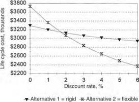
FIGURE 3.59 Sensitivity analysis showing effect of discount rate selection on life cycle cost of pavement alternatives.

shown in Table 3.29, the discount rate was unrealistically assumed as zero. Figure 3.59 shows the effect of discount rates from 0 to 6 percent. As is typically the case, the analysis is very sensitive to the discount rate. In this example, the rigid pavement pro­vides the lower life cycle cost when the discount rate is less than about 1.7 percent, and the flexible pavement when the rate is higher. It is apparent that the discount rate must be selected with great care.

Microsurfacing

Microsurfacing is the application of a thin cold-applied paving mixture composed of polymer-modified asphalt emulsion, 100 percent crushed aggregate, mineral filler, water, and other additives. A self-propelled continuous loading machine or a truck-mounted machine is used to proportion and mix the materials and apply the mixture to the pave­ment surface. Microsurfacing is used to retard raveling and oxidation, fill ruts, reduce the intrusion of water, improve surface friction, and remove minor surface irregularities.

The following conditions should be given careful consideration prior to microsurfacing:

• Localized wheel track cracking or edge cracking (see Figs. 3.57 and 3.58) should be repaired full depth.

• Any potholes must be repaired full depth.

• Areas which exhibit debonding must be patched.

• All existing patches must be in good repair.

• All existing cracks must be sealed.

• Crack sealing is not an acceptable treatment for cracks wider than 1 in (25 mm) as these cracks should be addressed with partial depth repairs.

Microsurfacing is suitable for all traffic levels. However, where ADT is greater than 10,000 vehicles/day, a double application of microsurfacing is required. This requirement is to ensure the wearing surface is durable throughout the intended design life.

Microsurfacing

FIGURE 3.57 Localized wheel track and edge cracking.

Microsurfacing

FIGURE 3.58 Localized edge cracking.

Fog Sealing

A fog seal is an application of a diluted asphalt emulsion to a weathered asphalt surface. It is used to seal and enrich the surface, seal out moisture, close up hairline cracks, and prevent oxidation and raveling. Fog seals are generally restricted to low-volume, low-speed roadways and parking lots, as they have a tendency to cause loss of friction for a short period of time after application. Fog seals should only be used on suffi­ciently weathered pavements that have the ability to absorb the asphalt emulsion. Fog seals should be placed on dry, clean pavements, when temperatures are warm or hot. Traffic should be kept off the fog seal until the emulsion has cured. Up to 3 h may be necessary to ensure sufficient cure. Fog seals can be expected to last as long as 3 years.

3.10.1 Chip Sealing

Chip seal is a sprayed application of a polymer-modified asphalt binder covered immediately by a washed limestone, dolomite aggregate, or trap rock and rolled with a

pneumatic roller. The binder is applied by an approved bituminous distributor, and the aggregate placed by an approved aggregate spreader. The rolling operation is intended to seat the aggregate into the binder and ensure chip retention. Chip seals can be placed as single or double applications, depending on pavement condition. Chip seal is most generally applied to low-volume roadways, but has been applied to roadways with average daily traffic levels (ADTs) as high as 30,000. Chip seals are intended to pro­vide a new wearing surface as well as to eliminate raveling, retard oxidation, reduce the intrusion of water, improve surface friction, and seal cracks.

Chip seals should only be applied to pavements that are structurally sound and suit­able for preventive maintenance. The following conditions should be given careful consideration prior to a chip seal:

• Localized wheel track cracking should be repaired full depth.

• Any potholes must be repaired full depth.

• Areas which exhibit debonding must be patched partial depth.

• All existing patches must be in good repair prior to chip sealing.

• All existing cracks must be crack-sealed prior to chip sealing.

• Localized high-severity edge cracking must be repaired full depth (see Fig. 3.56) prior to a chip seal.

• Rutting must be no more than 1/8 in (3 mm) deep.

Traffic should be restricted and speeds reduced to minimize the loss of chips from the pavement surface. Length of time for traffic restrictions depends largely on ambient weather conditions at the time of construction of the chip seal. The construction season for this work is relatively short. Chip seals should not be placed in cool weather. It usually requires about 1 month of warm weather following construction for the aggregate

Fog Sealing

FIGURE 3.56 Localized edge cracking must be repaired full depth before chip sealing.

particles to become reoriented and properly embedded in the asphalt membrane. The expected service life of a chip seal is 5 to 7 years.

Crack Sealing

Crack sealing is the placement of a sealant into existing cracks of a pavement. The sealant is made of a mixture of a neat or modified asphalt cement binder, with a number of possible additives such as rubber, polyester or polypropylene fibers, or polymers. Crack sealing can be placed into routed crack reservoirs using backer rods (see Fig. 3.6) or can be placed directly over the crack using an overband technique. Crack sealing is used to minimize the intrusion of water into the pavement. By keeping water out of the pavement, erosion of the mix is kept to a minimum, deterioration of the crack is slowed, and less water is available to saturate the base materials.

There is a wide window of opportunity for cost-effective crack sealing of flexible or composite pavements. In general, cracks that display significant raveling of the crack face and secondary branch cracking (see Fig. 3.54) need more than just a crack seal and should be considered for some other type of preventive maintenance, which may include crack sealing.

Crack Sealing

FIGURE 3.54 Secondary cracking of asphalt surface.

Rigid pavements are not expected to have cracks wider than hairline. Crack sealing hairline cracks in a rigid pavement has not been shown to be cost effective (see Fig. 3.55), and will result in a noisier and rougher riding pavement. Where cracks are found to be wider than 1/8 in (3 mm) and less than 1/4 in (6 mm), crack sealing may be beneficial; however, further investigation is recommended, as more serious problems may be present.

Best practice is to select pavements that have sufficient cracking for crack sealing mobilization to be worthwhile, yet preclude excessively cracked pavements. Furthermore, pavements that require the use of crack sealing material in excess of 5000 lb/lane mile (1400 kg/lane km) are questionable candidates for crack sealing.

Crack Sealing

FIGURE 3.55 Hairline crack in rigid pavement.

TABLE 3.28 Rubber-Asphalt Joint Sealing Compound Quantities Needed for Different Depths and Widths of Openings

Pounds required per 100 lineal ft for indicated width of opening

in

К in

38 in

V-2 in

58 in

% in

78 in

1 in

34

8.3

12.4

16.5

20.6

24.8

28.9

33.0

78

9.6

14.4

19.3

25.0

28.9

33.7

38.5

1

11.0

16.5

22.0

27.5

33.0

38.5

44.0

1%

12.4

18.6

22.8

31.0

37.2

43.3

49.5

1%

13.8

20.7

27.5

34.4

41.3

48.1

55.0

138

15.2

23.8

30.3

37.8

45.4

52.9

60.5

118

16.5

24.8

33.0

41.3

49.5

57.8

66.0

158

17.9

26.8

35.8

44.7

53.6

63.5

72.5

134

19.3

28.9

38.5

48.1

57.8

67.4

77.0

178

20.6

30.9

41.3

52.5

61.9

73.2

82.5

2

22.0

33.0

44.0

55.0

66.0

77.0

88.0

Conversions: 1 in

= 25.4 mm,

1 ft = 0.305

m, 1 lb

= 0.454 kg.

Where crack sealing is not a suitable method of preventive maintenance, other forms of pavement preservation should be considered. Table 3.28 is provided for quantity esti­mation. The table is based on a unit material weight of 63 lb/ft3 (1000 kg/m3), and does not account for waste or spillage. This table is applicable for crack sealing materi­als meeting the requirements of ASTM D-6690.

Maintenance of traffic is required to apply the sealant and allow it to cure. Cure time is usually less than 1 h. Crack sealing operations are most effective when pavement temperatures are cool to cold. As pavements cool they contract, and thus widen the cracks, allowing more sealant to enter the pavement. Crack sealing should not be done on wet or damp pavements and should be applied on pavements when both surface temperature and ambient air temperature are above 40°F (4°C).

Crack sealing will have little effect on the current pavement condition. The intent of crack sealing is to slow the rate of deterioration and prolong pavement life. Crack sealants are expected to last 2 to 3 years before reapplication is necessary.

PAVEMENT PREVENTIVE MAINTENANCE

Preventive maintenance (PM) is a cost-effective strategy of early maintenance done to a pavement as a preemptive measure to preserve the pavement by retarding deterioration. PM is traditionally a low-cost treatment done early in a pavement’s deterioration cycle. By definition, pavement preventive maintenance extends the service life and maintains or improves the functional condition of the system without substantially increasing struc­tural capacity.

Pavement PM treatments reduce the amount of water infiltrating the pavement structure and correct surface deficiencies such as roughness and non-load-related distress. These treatments contribute little or no improvement to the pavement structure. PM should never be applied if fatigue-related distress exists in the pavement.

If applied at the proper time, pavement PM will lower the life cycle cost of any given pavement section, and when applied on a network of pavements, will improve the system condition at a lower cost. Some of the more common pavement preventive maintenance treatments are discussed in Arts. 3.10.1 to 3.10.4.

Rehabilitation of Flexible Pavement

Asphalt Overlay. Without question the most common method of rehabilitation for flexible pavement is an asphalt overlay. There are many variations of this technique ranging from pavement planing and a thick asphalt overlay to a thin skin patch placed infrequently along a pavement. The existing condition of the asphalt pavement and the results of nondestructive testing dictate the most economical strategy. The pavement can be designed as a layered system.

Whitetopping. The construction of a concrete pavement on an existing asphalt pave­ment is termed whitetopping. An asphalt pavement provides an excellent base for a rigid pavement. The concrete pavement is designed as if it were a new pavement con­structed on an asphalt base. The AASHTO design procedure can be used to design the concrete pavement, and the strength of existing pavement is utilized. A concrete overlay is an acceptable rehabilitation technique for flexible pavements beyond economical repair. However, construction is difficult unless lane lines are shifted permanently, and the thickness of the overlay makes elevation transitions at bridges difficult.

METHODS OF PAVEMENT REHABILITATION

Once a pavement is determined to have unacceptable smoothness or has lost its ability to properly transport goods, it is reasonable to determine the best strategy to return the pavement to its original intended function. Many of the decisions that define the point where corrective action should be taken are management decisions and can be addressed properly only in a comprehensive study of pavement management data. Many considerations must be addressed before determining a list of good rehabilitation options. Leading rehabilitation techniques are reviewed in the following articles.

3.9.1 Rehabilitation of Rigid Pavement

CPR. The most common method of restoration for jointed pavement, both reinforced and nonreinforced, is termed concrete pavement restoration (CPR). CPR includes load transfer, restoration, joint removal and replacement, construction of rigid shoulders (if not already present), profile grinding to reestablish smoothness, and usually resealing joints and sealing any cracks. The CPR technique is only used when nondestructive testing measurements indicate that an asphalt overlay is not needed for the future

METHODS OF PAVEMENT REHABILITATION

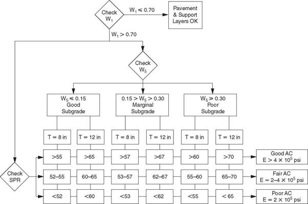
FIGURE 3.52 Evaluation of thick (thickness 8 to 12 in or 200 to 300 mm) flexible pavements from Dynaflect measurements. Conversion: 1 psi = 6.895 X 10⁻³ MPa. (From К. Majidzadeh and V. Kumar, Manual of Operation and Use of Dynaflect for Pavement Evaluation, Resource International, Inc., Columbus, Ohio, Report No. FHWA/OH-83/004, October 1983, with permission)


Подпись: 297

METHODS OF PAVEMENT REHABILITATION

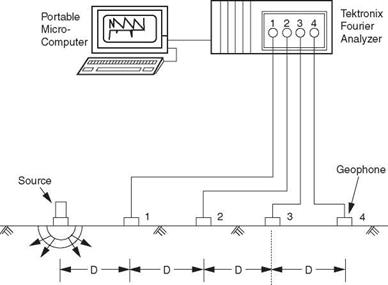
FIGURE 3.53 Schematic diagram of spectral analysis of surface waves (SASW) testing setup. (From S. Nazarian, D. Yuan, and M. R. Baker, Rapid Determination of Moduli with Spectral-Analysis-of-Surface-Waves Method, The University of Texas at El Paso, El Paso, Texas, Report No. TX-94 1243-1, November 1995, with permission)

design traffic. The disadvantage of this type of treatment is that, if the joints are not repaired properly, they will fail prematurely. Joint repair quantities are difficult to esti­mate, because joints continue to fail between the time the rehabilitation was designed and the time construction begins. The advantage of this type of treatment is that it utilizes the strength of existing pavement rather than an overlay, so overhead clearance problems are postponed or eliminated.

Repair and Overlay. When nondestructive testing measurements indicate that the existing slab thickness is insufficient to carry future design traffic, a common tech­nique is to repair failed joints or pavement and add an asphalt overlay. Generally, rigid repairs are preferred over flexible repairs. Flexible repairs in a rigid pavement do nothing to reestablish load transfer across the failed joint. Flexible repairs also have a tendency to heave because they are weak in compression and the rigid pavements expand during hot weather. Flexible repairs allow joints to open up beyond the design of the joint sealant, causing the joint sealant to fail. Finally, flexible repairs reduce pressure in a pavement and allow midpanel cracks to open up and lose aggregate inter­lock. The advantages of flexible repairs are the favorable cost and construction time. Disadvantages of rigid repairs include the construction complexity and time. It is important to realize that the biggest drawback of the repair and overlay strategy is the inability to estimate the amount of repair required at each pavement failure and, for jointed pavements, the number of joints that need repair. Designed overlays are usually thin (3 to 6 in or 75 to 150 mm). In cold climates, joints usually reflect through the overlay after one or two winters. Joint reflection cracking can be addressed by sawing and sealing a joint in the asphalt overlay at the exact same location as the joint in the underlying rigid pavement. Failure to align the flexible joint with the rigid joint will result in premature joint spalling of the asphalt layer.

Bonded Concrete Overlay. Another technique to increase pavement structural capacity is to bond additional concrete to the surface of the existing concrete pavement. The required overlay thickness is determined by subtracting the effective thickness, determined by nondestructive testing of the pavement, from the thickness required for a new pavement. Cracks in the underlying pavement will reflect through the overlay. Therefore, all joints and working cracks must be established in the overlay directly over joints and cracks in the existing pavement. For CRC pavement, this is generally not a concern. The existing pavement must be cleaned to ensure a proper bond. This technique is advised only for pavements that are in sound condition with little distress. Any areas showing deterioration must be repaired prior to the overlay.

Break and Seat for JRCP. The break and seat method for jointed reinforced concrete

pavement is accomplished by breaking the long slabs into shorter slabs to distribute the expansion and contraction movement of the pavement over more cracks or joints. This reduces the strains in the asphalt overlay over the cracks or joints to the point where reflective cracking is retarded. The smaller slabs are seated in the subgrade by rolling to reduce vertical deflections. The overlay is designed as a new flexible pave­ment section with the broken and seated pavement as a base. The broken and seated pavement is given a structural coefficient as determined by nondestructive testing. One disadvantage of this technique is that, to fail or debond the reinforcing steel, tremen­dous breaking effort is required, and this results in a weak and nonuniform base. Where the reinforcing steel is not failed or debonded, large slabs continue to behave as large slabs, causing the joints to reflect through the overlay. Additionally, breaking does not correct problems at joints. Failed joints continue to be weak points in the pavement and usually heave, creating a hump in the overlay. The advantage to this technique is that broken and seated pavements tend to require thick overlays and maintain a high level of serviceability. Additionally, reflective cracking is of low severity when compared with cracking in thin asphalt overlays.

Crack and Seat for JPCP. The crack and seat method for plain concrete pavement (nonreinforced) is accomplished by producing several transverse cracks in each slab, thus transforming the long slabs into shorter slabs to distribute the expansion and con­traction movement. This reduces the strains in the asphalt overlay over the joints to the point where reflective cracking is retarded, and the smaller slabs are seated in the subgrade to reduce vertical deflections. By definition, crack and seat produces a crack visible when the pavement is wetted with water. As with break and seat, the overlay is designed as a new flexible pavement section with the cracked and seated pavement as a base, and with a structural coefficient as determined by nondestructive testing. The disadvantage of this method is that the cracking does not correct problems at joints. Joints that have failed continue to be weak points in the pavement and usually heave, creating a hump in the overlay. The advantage of this method is that cracked and seated pavements with thick overlays (7 in or more) exhibit a high level of serviceability, and reflective cracking is of low severity when compared with cracking in thin asphalt overlays.

Rubblize and Roll. Rubblize and roll is applicable for all types of rigid pavement. This method is accomplished by breaking the existing pavement into 6 in (152 mm) size or less using a resonant beam breaker or multihead breaker. The rubblized concrete is compacted with a roller and used as a base for a new pavement. The overlay is designed as a new flexible pavement section with the rubblized and rolled pavement as a base. The rubblized pavement is given a structural coefficient based on nondestruc­tive testing. One disadvantage of this technique is that rubblizing weakens the pavement and thereby increases the required overlay thickness. Areas with soft subgrade require removal of the pavement and undercutting; otherwise, the rubblization process cannot be achieved properly. The geometry of the equipment prohibits breaking near portable barriers used for traffic control. Another disadvantage of this technique is that, because the resulting overlay is thick, elevation transitions at bridges require pavement replacement. One advantage of this technique is the complete utilization of the exist­ing pavement as a uniform base without discontinuities. For reinforced concrete pave­ment, the technique serves to completely debond the steel from the concrete.

Thick Asphalt Overlay with No Repairs. A thick asphalt overlay with no repairs is a quick and inexpensive rehabilitation strategy that can be used on any rigid pavement beyond eco­nomical repair. As the overlay thickness is increased, vertical deflection is decreased as a result of the increased structure. Horizontal movements in the slab are decreased because of lower temperature variations. This decreases the strain at the interface of the over­lay and pavement, which retards reflective cracking. The overlay is designed as a new flexible pavement section with the existing pavement as a base. The existing pavement is given a structural coefficient based on deflection testing. A disadvantage of this strategy is that problems at joints are not corrected. Joints that have failed continue to be weak points in the pavement. Another disadvantage is that the thick overlay neces­sitates pavement replacement to make elevation transitions at bridges. The advantages of this strategy are the low initial cost and ease of construction. Reflective cracking is of low severity when compared with cracking in thin asphalt overlays.

Unbonded Concrete Overlay. The purpose of breaking the bond between the old pavement and the proposed overlay is to separate the distresses in the old pavement from the new concrete overlay. Thus, the concrete overlay can be treated as a separate pavement, and the existing distressed pavement as a uniform base. There is little bene­fit derived from repairing the existing pavement prior to placing the overlay, as the bondbreaker will provide uniform support and interface for the concrete overlay. The bond – breaker is placed as a thin (1- to 3-in) asphalt overlay on the existing pavement, and the concrete overlay is placed on the bondbreaker. The thickness required for the concrete overlay can be determined using the following modified version of an equation developed by the Army Corps of Engineers:

T = V(RT)2 – (ET)2 (3.8)

where T = the required thickness of the concrete overlay, in (mm)

RT = required thickness of new concrete pavement on the existing subgrade and for the anticipated truck loading, in (mm); the existing subgrade strength can be determined from original construction and design records or from nondestructive testing

ET = effective thickness of existing concrete pavement as determined by non­destructive testing, in (mm)

This technique is most efficient if the entire width of the roadway is available for overlay at the same time, but this makes maintenance of traffic difficult. However, the strength of the existing pavement is utilized, and the performance can be expected to be similar to that of a new pavement.