Category A HOUSE

CUTTING SQUARE WITHOUT A SQUARE

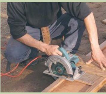
One of the most important skills a carpenter learns over the years is train­ing and trusting his or her eye. And one of the best ways to develop this capability is to cut square by eye. Instead of using a square to mark a 90- degree cutoff line on a board, simply make a quick pencil mark for length on the board, line up a circular saw, and make the cut. Over the course of framing a floor or a wall, this method can save you plenty of time.

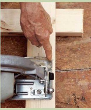
If you’re comfortable using a circular saw, it’s not difficult to master this technique. Position the saw with the blade aligned on the cutoff mark and the front of the saw’s base parallel with the edge of the board. As you make the cut, keep the base parallel with the board’s edge. Practice a few times on scrap, check each cut, and adjust the angle of the cut until you’ve got it right. In time, you’ll develop a “feel" for square.

Make square cuts by eye. To make a square cut, put the blade on the cut line and keep the front edge of the saw base parallel with the board.

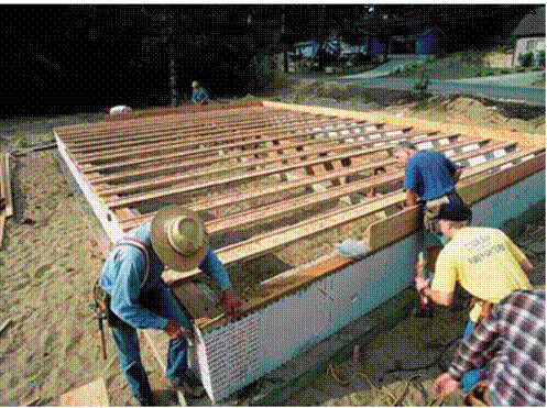
This is an easy way to spot layout mistakes. Take the time to check the framing against the details shown on the plans. Corrections are much easier to make now than after the floor sheathing is installed. Enjoy the moment. Joists on edge are beautiful in their own right, clearly and unmistakably showing the promise of a new building.

STEP 7 INSTALL EXTRA JOISTS AND BLOCKING

Until recently, extra joists were often required under walls that ran parallel to the joists, because they helped support the roof structure. Most houses built these days use roof trusses, however, which are engineered to span from outside wall to outside wall without the need for interior support. There usually isn’t a need to in­stall extra joists under walls, though some local codes still require them. Check with your town or city building department to make sure.

CUTTING SQUARE WITHOUT A SQUARECUTTING SQUARE WITHOUT A SQUAREПодпись:Similarly, wood or metal bridging is no lon­ger required. Installed in crossed pairs between

I-JOIST CUTTING GUIDE

I-JOIST CUTTING GUIDEI-joists are awkward to cut because the top and bottom chords are wider than the web. To overcome this difficulty, make a simple jig with 3/4-in.-thick plywood. Cut a rectangular piece of plywood to fit between the chords and serve as the base of the jig. Screw a longer piece to the first piece, positioning it to guide a 90-degree cut. The edge of the top piece guides the base of the circular saw, as shown in the photo at right. Lay the guide on the I-joist, set the saw on it, and make a square cut. It’s that simple.

Cut I-joists with a guide. Scrap sheathing that is nailed or screwed together creates an effective guide for cutting I-joists. [Photo by Roe A. Osborn, courtesy Fine Homebuilding magazine © The Taunton Press, Inc.]
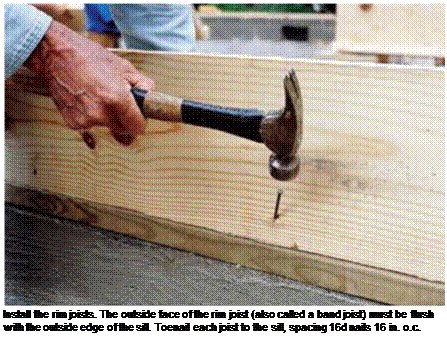
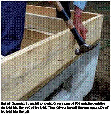
Подпись: Install the rim joists. The outside face of the rim joist (also called a band joist) must be flush with the outside edge of the sill. Toenail each joist to the sill, spacing 16d nails 16 in. o.c.

swell, shrink, crack, or warp the way solid lumber does. They are much lighter and easier to carry than 2x joists. And they’re uniform in size. In a load of 2x joists, you might find up to 3/8 in. of variation in joist width. I-joists don’t vary; once installed, they create a dead – level floor. Nails driven through the sheathing into the top chord are less likely to come loose and create a squeaky floor, especially when the sheathing is applied with adhesive. In terms of price, they are competitive with standard-

dimension lumber. Installation details for I-joists are slightly different than those for 2x joists. I’ll cover those differences just ahead.

Nail rim joists first

Rim joists form the exterior of the building and are the first joists to be installed. The layout of other joist locations are marked on the top edges of the rim joists. Cut the rim joists to length and toenail each one flush with the outside of the sill. I drive one 16d nail every 16 in. around the perimeter (see the photo at left). Don’t forget that nails going into PT wood should be hot-dipped galvanized. In earthquake and high-wind areas, code may require that the rim also be secured to the sill with framing anchors, so check with your local building inspector. If there are no vents in the foundation, they can be cut into the rim joists. A standard screened vent fits in a 4//2-in. by 14//2-in. opening.

If you’re framing a floor with I-joists, you’ll probably use the specially made OSB rim joists supplied with your I-joist order. Install rim joists along only one side of the house. Then lay the I-joists flat across the sills, butting the end of each joist fast against the installed rim joist. The opposite ends of the joists will extend over the sill at the other side of the house. You can now

snap a line across the ends to establish where the I-joists need to be cut. A simple jig, explained in the sidebar on the facing page, makes it easy to cut the joists smoothly and accurately. After cutting the I-joists to length, complete the rim joist installation.

Joist layout goes quickly

When a single joist spans a house from edge to edge, the layout is identical on parallel rims. Just hook a long tape on the end of the rim joist and make a mark on top every 16 in. (32 in., 48 in., etc.) down the entire length. Put an “X” next to each mark to indicate which side of the line the joist goes on.

When the joists lap over a central girder or wall, the layout on the opposing rim joists must be staggered. On one rim joist, mark the 16-in. o. c. locations with an “X” to the right; on the opposite side, lay out the joists with an “X” to the left. This allows the joists to lap and nail over a girder or crib wall, where they will be stabilized with blocks (see the illustration on p. 68).
Подпись:

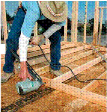
I-JOIST CUTTING GUIDE Подпись: With a little training, almost everyone can learn to safely use a nail gun to frame walls, though a trained professional or an experienced volunteer under supervision should use them. [Photo by Don Charles Blom]

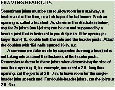
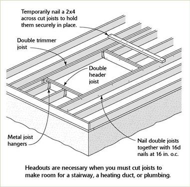
I-JOIST CUTTING GUIDEYour joist layout may include openings (called headouts) for a stairway or to provide clearance for plumbing or vents. Your plans should show these openings, but it’s always a good idea (and it could save a lot of time and effort) to check with the plumber. A common mistake is leaving insufficient room between

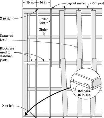
Подпись: IIII III III III III III III III III II III III III III III III III III II III III III III III III III III II III III III III III III III II III III III III III III III III II III III III III III III III III II III III II JOIST LAYOUT I-JOIST CUTTING GUIDERoll and nail the joists

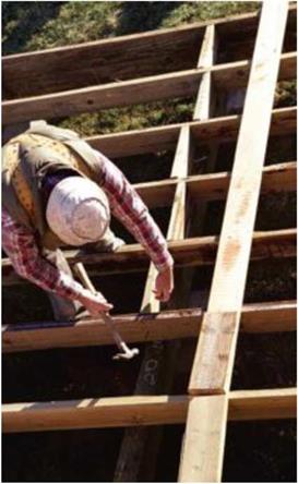
Once the joists are cut to length and in position, carpenters say that it’s time to “roll” them. This just means setting the joists on edge, aligning them with their layout, and nailing them in place. If you are working with 2x joists, it’s im­portant to sight down each joist to see whether there’s a bow or a crown, and then set the joist with the crown facing up.

Drive two 16d nails through the rim joist directly into the end of the joist—one nail near the top and one near the bottom (see the photo below). Most codes also require that joists be toenailed (one 16d on each side) to the sill plates and supporting girders. To nail off an I-joist, drive a 16d nail through the rim joist and into each chord, then nail the chord to the sill on both sides of the web.

Make sure that all the joists are nailed securely. This is important for safety reasons, for quality workmanship, and for meeting code requirements. Once all the joists are nailed upright, stop and check for symmetry—make sure the line of one joist is parallel with another.

I-JOIST CUTTING GUIDE

Подпись: If a single joist spans from rim to rim, the layout is identical on each rim. When joists lap midspan, the layout on opposing rim joists must be staggered.
Подпись: Blocking adds strength. Install blocking between joists directly over the midspan support. Nail the blocking to the joists and to the top of the girder or crib wall.the joists for the tub’s trap and the toilet’s drain. You may need to frame a headout to make room for plumbing. For headout framing details, see the sidebar on p. 67. When framing with I-joists, remember that, like any other type of engineered joist, they cannot be notched or cut midspan with­out destroying their structural integrity.

Cut the joists in place
Подпись:If you trust your eye, try cutting 2x joists in place rather than measuring each one indi­vidually. As you become comfortable using a circular saw, you’ll be able make a square cut without using a square (see the sidebar on the facing page). This technique is definitely worth learning. Over the course of framing a house, it will save a significant amount of time.
TOENAILING BASICS

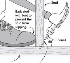
TOENAILING BASICSПодпись: Bottom plate Start the nail at a 60° angle, about 1 in. from the end of the board. Подпись: When it's not possible to drive a nail directly through one piece of wood and into another, join them with a toenail.Driving a couple of nails through the side of one 2x into the edge or face of another creates a strong connection. This is a good way to join two 2xs at a right angle. But sometimes this isn’t possible, either because the board is too thick or because its face is not exposed. That’s when you resort to driving a nail at an angle, or toenailing.

To toenail two boards together, hold the nail at a 60-degree angle and start it about 1 in. from the end of the board. If the nail angle is not correct, the connection between the two pieces of wood will not be as strong. Back up the wood with your foot to hold the board in place as you toenail. With practice, you’ll soon gain skill, speed, and confidence.

Подпись: The girders that support the joists need to break over a post. [Photo by Don Charles Blom]

attaches to the pier post and holds it in position. Secure a TT-in.-thick pressure-treated pad to the top of the pier if the posts will be cut from untreated lumber. You can measure for the post’s length just as you measured for the crib wall’s studs, stretching a line above a piece of girder stock placed on the pier. Cut your posts to length, then secure them directly to the piers or toenail them to the blocks attached to the piers. Make sure the posts are plumb and paral­lel to one another.

Girders must butt together over a post. When the end of a girder fits into a pocket in the foun­dation, you’ll have to shim up the girder to get the top surface level with the top of the sill. The shims used beneath girders will bear the full weight of the floor, so they must be cut carefully from pressure-treated stock. Cut uniformly thick shims instead of tapered ones and make them large enough to fit in the bottom of the founda­tion pocket. Rather than foundation pockets, we inserted a metal 4x post base in the footing next to the stem wall to hold the end of the girder.

Подпись: Plywood gussets tie girders securely to their post supports. [Photo by Don Charles Blom] Подпись: Patterns save time. When cutting multiple identical pieces of framing mem-bers, such as joists, it is common to use a pattern piece. Cut one piece to the correct length, then lay it on top of the next piece to be cut and mark that one. Write the word “pattern” on the original piece. Подпись: Because of concrete’s ability to absorb mois-ture, code requires that the end of the girder be held about Vi in. away from the back of the pocket when cutting the girder to fit. If you’re not using pressure-treated stock for the girder, you can wrap the end of the girder with builder’s felt or sheet metal to give it some protection against moisture damage. Toenail the girders to the posts with either four 8d or three 16d nails. Now brace the posts and splice the girders by nailing the plywood gussets on both sides of the joint (see the illustration on p. 48). STEP 6 INSTALL THE JOISTS Подпись: Joists span a house from edge to edge, providing support (and a nailing surface) for the subfloor and a platform for the walls. Many older houses were built with undersized joists that were unable to keep floors and ceilings from sagging. Building codes today help ensure that joist sizing and spacing are more than adequate to keep floors rock solid yet resilient. Joists are normally spaced to allow for the most efficient use of full-size (4-ft. by 8-ft.) sheets of OSB or plywood. Joists cut from 2x lumber are generally spaced 16 in. or 24 in. o.c. Engineered wood I-joists can be spaced on centers of 12 in., 16 in., 19.2 in., or 24 in.Solid lumber versus engineered I-joists

Up until 20 years ago, most of the floors in this country were built with standard 2x joists. These days, more floors are being built with engineered I-joists. So named because of their “I” profile, I-joists have plywood top and bottom chords connected by an OSB web (see the top left photo on p. 62). They offer several advan­tages over solid lumber. Being an engineered product, they are knot-free and can span long distances without interior support. I-joists don’t

PNEUMATIC NAILERS

Volunteers who help build Habitat houses use only hammers to drive nails. But these days, buildings are nailed together with all kinds of pneumatic nailers. These are good, reliable tools, available for framing, finish work, siding, and shingling. However, there are basic safety considerations to keep in mind.

■ Treat a pneumatic nailer with respect. Be mindful of what you are doing. Never point a nailer at yourself or at others.

■ Read and follow the instruction manual regarding its maintenance and use.

■ Don’t walk around with your finger on the trigger. You could acci­dentally fire a nail.

■ Adjust the air pressure as needed. Larger nails require more pressure.

■ Wear safety glasses or goggles.

■ Disconnect the nailer from the air compressor before clearing a jammed nail.

■ When nailing on a sidewall, don’t hold the nailer in front of your face. Hitting a metal strap or other hardware beneath the surface could cause the nailer to recoil into your face with considerable force.

■ Drain moisture from the compressor tank after using it. A rusty, compromised tank can explode under pressure.

■ No one under 18 years of age should use a pneumatic nailer.

■ Pneumatic nailers should only be used by a trained professional or an experienced volunteer under supervision.

STEP 5 BUILD MIDSPAN SUPPORT FOR JOISTS

Unless you are building on a slab, you’ll prob­ably need to provide midspan support for the floor joists. Without additional support some­where between the sills, the joists can be over­spanned, resulting in a finished floor that sags or feels bouncy. A friend once took me through

STEP 5 BUILD MIDSPAN SUPPORT FOR JOISTS

Use sill seal to block drafts and insects. Installed between the sill and the foundation, sill seal provides a resilient layer of insulation, filling in small gaps and helping maintain an effective barrier between indoors and out.

[Photo © Mike Guertin]


his 18th-century home in rural Connecticut. The beautiful, hand-hewn floor joists in the basement were fascinating—dry, free from rot and termites—but far overspanned. Upstairs, it felt like walking on ocean waves. Clearly, what was needed was some support to keep the joists from sagging and bouncing in the middle.

Codes require a minimum of 18 in. between the earth and the joists in a crawl space. These days, two systems are commonly used to provide midspan support for the joists: crib walls (also called pony walls) and post-and-girder systems. A crib wall is just a shortened version of a regu­lar stud wall and is supported along a continu­ous concrete footing. With a post-and-girder system, a solid or built-up girder (also called a beam) is supported by posts every 6 ft. or so, depending on code. The girder usually fits into a recess or pocket where it meets the foundation wall. Joined to the girder by metal connectors or plywood gussets, the posts bear on concrete piers (see the illustration on p. 48).

In both these systems, the joists rest on and are nailed to the top support member.

Подпись:The width of the joists and the length of the span determine how much support is needed. With 2×6 joists, for example, posts and girders are often placed every 6 ft. With 2 x12s or
STEP 5 BUILD MIDSPAN SUPPORT FOR JOISTS

STEP 5 BUILD MIDSPAN SUPPORT FOR JOISTS STEP 5 BUILD MIDSPAN SUPPORT FOR JOISTS
STEP 5 BUILD MIDSPAN SUPPORT FOR JOISTS

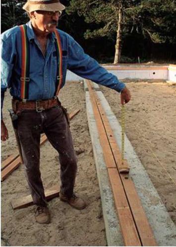
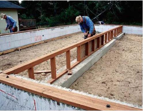
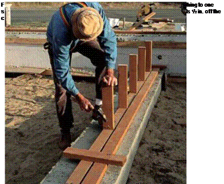
Build a crib wall. It’s best to use PT wood in underfloor areas. Crib walls (also referred to as pony walls) are short, stud-framed walls and can provide midspan support for joists that extend over a crawl space. After bolting the wall’s bottom plate to the footing, stretch a line over the sills to measure the length of the crib wall’s studs (see the photo above). Place two pieces of top plate stock on the wall’s bottom plate and measure up to the line. Toenail the studs to the bottom plate, spacing them 16 in. o. c. or 24 in. o. c. depending on your code requirements (see the photo below). [Photos © Memo Jasso]

Подпись: Ill III III III III III III III III III III II III III III III III III III III III III III III III III II III III III III III III III III III III III III III II III III III III III III III III III III III III III III II III III III III III III III III III III III III III II III MEASURING POST OR PONY-WALL STUD LENGTHS STEP 5 BUILD MIDSPAN SUPPORT FOR JOISTSWait to carpet over concrete. Make sure you let a con­crete slab dry out well (for several months) before laying carpet on it. If you don’t, the carpet adhesive may not hold properly and your carpet could rot, possibly posing a health hazard.

STEP 5 BUILD MIDSPAN SUPPORT FOR JOISTS

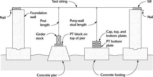
Stretch a string tightly from one sill to another. For the post length, measure from a piece of girder stock to the taut string. To find the stud lengths for a pony wall, measure from the top of a stack of three wall plates to the string.

engineered I-joists, only one support in the center may be needed.

Crib-wall construction

Just in case a moisture or termite problem develops in the future, I like to build crib walls with pressure-treated wood. To determine the length of the crib wall’s studs, first bolt the wall’s bottom plate to the footing. Then tightly stretch a string above the crib wall’s bottom plate and across the mudsills installed on the stem walls. Set two pieces of top plate stock on the bottom plate. The distance between the top plate stock and the string is the length of the crib wall’s studs (see the top right photo on the facing page).

Toenail the studs to the bottom plate, spac­ing them 24 in. o. c. but leaving a 30-in.-wide opening somewhere in the wall so that plumbers, electricians, and others can get from one side of the crawl space to the other. When toenailing the studs to the crib wall’s bottom plate, you can drive either four 8d toenails or three 16d nails per stud. If you’re using a pneumatic nailer,
make sure you follow the safety guidelines explained in the sidebar on p. 65.

Once the crib wall’s studs are in place, nail on the two top plates. Drive a pair of 16d nails through the first plate into the top of each stud. Secure the double top plate with a single 16d nail at each stud location, and toenail the plate’s ends to the sill on the foundation wall at each end of the house. I like to sheathe sections of a crib wall with pressure-treated plywood (my first choice) or OSB to provide good lateral bracing (see the bottom left photo on the facing page). Be sure not to sheathe over the crawl-through opening you framed in the wall. As an alternative to sheathing a crib wall, you can stiffen it with 2x diagonal braces nailed to the top and bottom plates and across at least one stud.

Build a post-and-girder system

Posts used to construct a post-and-girder system can be anchored directly to a metal post base that is set in the concrete footing. You can also use a precast pier with a metal strap that

Locate and drill bolt holes

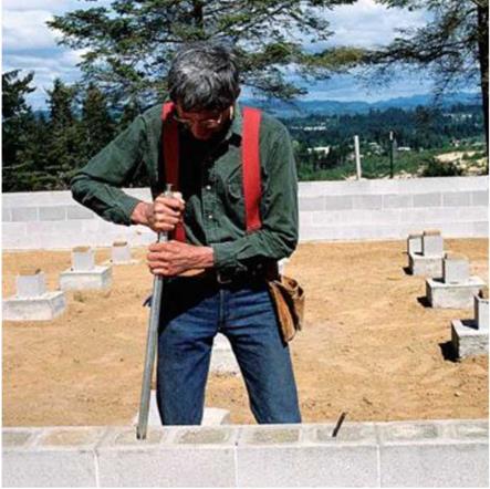
Anchor bolts sometimes come out of the foundation at odd angles. You can straighten bent bolts with a length of pipe, as shown in the photo at left. Then set long, straight, pressure-treated sill boards in place for mark­ing and drilling. You can use a square and a tape measure to lay out the bolt hole locations

Подпись: A long pipe straightens a short bolt. A length of 1-in.-dia. pipe straightens any bolts that may have been bent during (or since) the foundation pour. [Photo © Roger Turk]ІІІІШІІІІШШШШШШШШШІІШІШШШМШІМШІІІШІІІІІІШІІІШШІІІШІІШШШШШШШШІІІІМШШШШШІІШШШШІІІШШШШШШІІІІІІІІШШШШІМШШІІІ
POSITIONING SILLS ON THE FOUNDATION

Подпись:Locate and drill bolt holesSiding without sheathing

Locate and drill bolt holes

Nut and washer

Sill

Locate and drill bolt holes

Anchor

bolt

Locate and drill bolt holes

Concrete

foundation

ABC

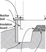
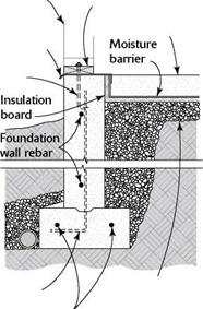
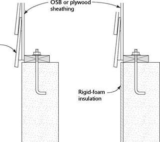
Sill plates can be set flush with the edge of the foundation (A) and the siding nailed directly to the walls. When sheathing the house frame with OSB or plywood, though, hold in the sill plates 1/2 in. (B). When using rigid foam to insulate a basement or a crawl space (C), position the plates so that the outside face of the sheathing is in plane with the outside face of the foam.

A bolt marker comes in handy. Use a bolt marker to transfer the bolt locations to the sills so you can drill the bolt holes accurately. [Photo by Don Charles Blom]


Locate and drill bolt holes

An electric drill is great for boring holes. Use a spade bit in an electric drill to bore bolt holes through a wood sill.


MAKING A BOLT-HOLE MARKER


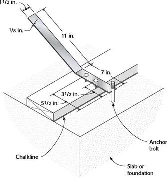
Select an 18-in. by 11/2-in. by 1/8-in. metal plate strap. Cut a notch in one end of the strap so that it will fit around a 1/2-in. or 5/8-in. bolt. From the center of the notch, measure back 31/2 in. for a 2×4 plate and 51/2 in. for a 2×6 plate. Drill holes at those points and insert 3/16-in. by 3/4-in. stove bolts. Put a bend in the plate strap to make it easier to use.


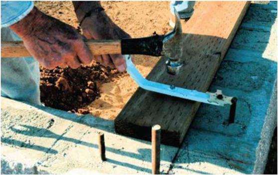
A bolt-hole marker makes it easy to transfer the bolt location to the sill in preparation for drilling a hole.


Locate and drill bolt holesLocate and drill bolt holes

z/2-in. bolts. For 5/8-in. bolts, use a 3/4-in. bit.

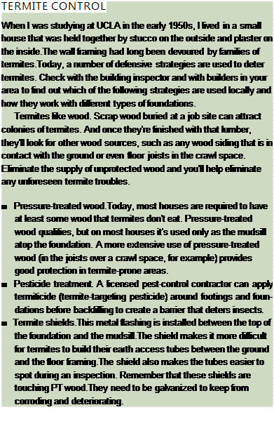
Подпись: TERMITE CONTROL When I was studying at UCLA in the early 1950s, I lived in a small house that was held together by stucco on the outside and plaster on the inside.The wall framing had long been devoured by families of termites.Today, a number of defensive strategies are used to deter termites. Check with the building inspector and with builders in your area to find out which of the following strategies are used locally and how they work with different types of foundations. Termites like wood. Scrap wood buried at a job site can attract colonies of termites. And once they're finished with that lumber, they'll look for other wood sources, such as any wood siding that is in contact with the ground or even floor joists in the crawl space. Eliminate the supply of unprotected wood and you'll help eliminate any unforeseen termite troubles. ■ Pressure-treated wood.Today, most houses are required to have at least some wood that termites don't eat. Pressure-treated wood qualifies, but on most houses it's used only as the mudsill atop the foundation. A more extensive use of pressure-treated wood (in the joists over a crawl space, for example) provides good protection in termite-prone areas. ■ Pesticide treatment. A licensed pest-control contractor can apply termiticide (termite-targeting pesticide) around footings and foundations before backfilling to create a barrier that deters insects. ■ Termite shields.This metal flashing is installed between the top of the foundation and the mudsill.The shield makes it more difficult for termites to build their earth access tubes between the ground and the floor framing.The shield also makes the tubes easier to spot during an inspection. Remember that these shields are touching PT wood.They need to be galvanized to keep from corroding and deteriorating.

on the sills, but it’s a lot faster to mark the hole locations with a bolt marker. You can make a bolt marker or buy a ready-made ver­sion (see the illustration on p. 59 and Resources on p. 279). To use this layout tool, place each plate directly on the inside of the chalkline.

Once the bolt locations are marked, set the sill plates on blocks of wood or sawhorses and drill the holes. Use a 5/8-in. bit to make holes for

Install sill seal and termite shields

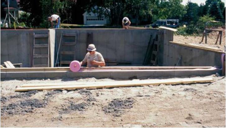
Sweep the foundation clean of debris, then put down a layer of sill seal insulation where the sills will be located (see the photo on the facing page). Sill seal does just what its name says. As an alter­native, you can run two heavy beads of silicone caulk between the sill plates and the foundation. This also prevents cold air leaks between the foundation and the sill. In areas where termite infestation is a possibility, you’ll also need to lay down a termite shield over the foundation bolts and under the sill. As shown in the illustrations on p. 50, the shield edges must extend beyond the foundation (including the foundation insulation) and the sill.

Place the sills over the bolts, put on the washers and nuts, and tighten the nuts with a crescent wrench, taking care to keep the inside edge of the sill on its layout. (Note: When work­ing on a slab, drill holes in the plates but leave them unbolted until after the wall is raised— see Chapter 4 for details.) Codes in earthquake and high-wind areas often require the use of larger washers (galvanized, /4 in. thick, and 2 in. square). These larger washers help secure the mudsill and keep it from splitting when under pressure from lateral forces.

If the measuring work you did at the begin­ning of this step told you that parts of the foun­dation were out of level, you can expect the sills to be that way, too. To correct slight discrepan­cies (up to /4 in. or so), you can insert pressure- treated shims underneath the sills. For larger errors, it’s best to call in a concrete contractor.

Determine the sill’s position

Depending on what you find after measuring the foundation, you may need to adjust the sill’s position using some of the techniques explained in the sidebar on p. 55. The sill plates are often bolted flush to the outside of the foundation, but there are variations you may want to consider (see the illustration on p. 58). For example, when the walls will be sheathed with ‘/i-in. plywood or OSB, it’s best to hold the plates Vi in. inside the founda­tion. This puts the sheathing flush with the foundation and allows the siding to lap down over the concrete.

The sills must be installed along snapped layout lines on top of the foundation walls. (If

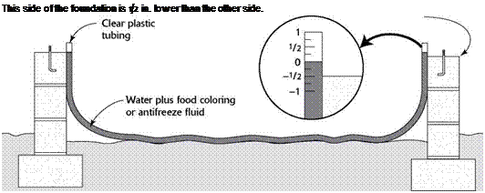
Подпись: This side of the foundation is 1/2 in. lower than the other side.

USING A WATER LEVEL

A simple water level can be used to check the foundation for level. These are available at home improvement centers. If the foundation is not level, the sill plate can be shimmed up with pressure-treated shims.

Determine the sill’s position

you’re building on a slab, the layout lines will be on top of the slab.) The lines identify where the inside edge of the sill will fit.

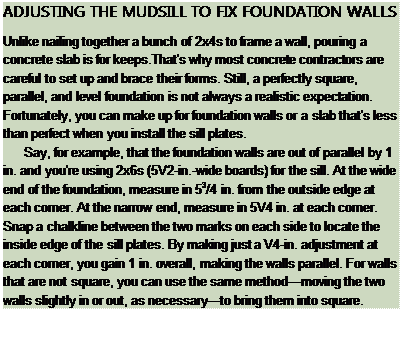
Taking the width of the sill lumber into account (31/2 in. for a 2×4 sill, 51/2 in. for a 2×6), snap chalklines around the perimeter to indicate the inside edge of the sill (see the photo on p. 56). Make slight adjustments in the positions of the chalklines, if necessary, so that the sill is straight, square, and parallel.

Foundation wall insulation

Foundation insulation isn’t used in mild cli­mates. But in areas with frigid winter months, it can improve interior comfort and save on heating costs. Even though it’s not required by code in many areas, it’s definitely worth install­ing wherever prolonged freezing temperatures are expected. You can install insulation on the inside or outside of a crawl-space or basement wall. Exterior insulation, in the form of rigid foam boards, is glued to the foundation walls before backfilling. Where they’re exposed above the finished grade on the exterior, insulation boards must be protected with siding material or stucco. It’s important to remember that any type of foundation insulation can provide a hid­den passageway for termites and other insects to enter the house. Make sure you cut off this passageway by installing a termite shield beneath the sill. As shown in the illustrations on pp. 50—51, the shield should be installed between the top of the foundation and the sill.

Drainage around the foundation

After you’ve taken care of the details, you can begin backfilling around the foundation. Along the footing, install perforated drainpipes in a bed of gravel several inches thick. Cover the pipe with at least several more inches of gravel. To prevent the drainage channel from silting up, cover the top layer of gravel with filter fabric before backfilling it with soil.

STEP 4 ATTACH THE SILLS

Подпись:Подпись: COMPENSATING FOR OUT-OF-PARALLEL WALLS Foundation wall insulationПодпись:Some important carpentry work is about to begin. Whether you are building on a concrete slab, over a crawl space, or over a full basement, the first wooden member that is laid down is called a sill, mudsill, or sole plate. This sill is commonly a pressure-treated 2×4 or 2×6 at­tached directly to the foundation with anchor bolts embedded in the concrete. Occasionally, it is attached with hardened concrete nails or steel pins shot through the sill and into the concrete by a power-actuated nailer.

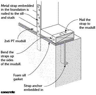
Подпись: IIII III III III III III III III II III III III III III III III II III III III III III III III II III III III III III III II III III III III III III III II III III III III III III III II III III III III III III III II III FASTENING MUDSILLS WITH METAL STRAPS Подпись: concrete Подпись: Metal straps can be embedded in the concrete foundation. After the bottom plate is down, the straps are nailed to it. Metal hardware creates a positive connection between the foundation and the house frame. This is especially important in earthquake and high-wind areas.Подпись: Take special care when working in a trench or around a basement wall. Dirt can cave in, fill a trench, and trap you under tons of earth. The rule of thumb is to never get in over your head!Подпись: Snap chalkline to lay out the sill. The line shows where the sill's inside edge rests. If the foundation isn't perfectly square, adjust the line's position so that the sills will be. [Photo by Roe A. Osborn, courtesy Fine Homebuilding magazine © The Taunton Press, Inc.] Most codes require that anchor bolts be located 1 ft. from each corner of the founda­tion, 1 ft. from the ends of each sill plate, and a maximum of 6 ft. o. c. everywhere else. These are minimum requirements. Builders living in earthquake or high-wind areas often use 5/8-in.-dia. anchor bolts rather than ‘A-in. bolts and reduce the spacing to 4 ft. o. c. or less. As mentioned in Chapter 1, it’s important to check with the local building inspector to ensure that the house you’re building meets or exceeds code.

Check the foundation first

Unfortunately, you can’t assume that your foundation is straight, parallel, square, and level. But here’s some good news: If you know how far off it is, you can usually make the appropriate corrections when installing the sills (see the sidebar on p. 55). It’s worth it to make the sills as straight, parallel, square, and level as possible. Otherwise, the mistakes made at this preliminary stage tend to become even more troublesome further down the line. Here’s how to check the foundation:

STRAIGHT. Check the walls for straightness by stretching a dry line (string) from corner to corner. At this point, you just need to know how straight the top outside edge of the foundation is, because you’ll be measuring in from this edge to locate the sill.

PARALLEL. Measure across the walls at both ends and in the middle. All three measurements should be the same. I use /4 in. over 20 ft. as the tolerance limit for parallel.

SQUARE. Plus or minus ‘/2 in. over 20 ft. is the tolerance that I use for square walls.

You can check any rectangular foundation for square simply by comparing the diagonal measurements, which should be equal. When that isn’t possible, use the 6-8-10 rule to check for square corners. Measure 6 ft. in from a corner on one side and 8 ft. on the other side (see the photo on the facing page). Then measure between those two points. If the corner is square, the hypotenuse of the triangle should be 10 ft. For smaller buildings, 3 ft. on

Подпись: Test for square. One way to test foundation corners for square is to measure 6 ft. from the outside corner along one side and 8 ft. along the other. If til e til ird side of the triangle measures exactly 10 ft., you have a right angle. [Photo © Roger Turk]

one side and 4 ft. on the other should yield a 5-ft. hypotenuse. On a large building, use measurements of 12 ft., 16 ft., and 20 ft.

LEVEL. I like to check a foundation for level with a builder’s level (especially one with a laser beam) set on a tripod. If you don’t have one of these available, an inexpensive water level will work fine (see the illustration below). The walls should be level to within V4 in. over 20 ft.

STEP 3 BACKFILL AROUND THE FOUNDATION

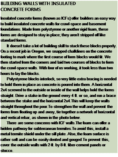
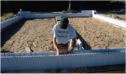
Подпись: BUILDING WALLS WITH INSULATED CONCRETE FORMS Insulated concrete forms (known as ICFs) offer builders an easy way to build insulated concrete walls for crawl-space and basement foundations. Made from polystyrene or another rigid foam, these forms are designed to stay in place; they aren't stripped off like standard forms. It doesn't take a lot of building skill to stack these blocks prop-erly. On a recent job in Oregon, we snapped chalklines on the concrete footing to mark where the first course of form blocks would fit. We then started from the corners and laid two courses of blocks to form the crawl-space walls. With four of us working, it took less than two hours to lay the blocks. Polystyrene blocks interlock, so very little extra bracing is need-ed to hold them in place as concrete is poured into them. A horizon-tal 2x4 screwed to the outside or inside of the wall helps hold the forms straight. Drive a stake in the ground every 4 ft. or so, and run a brace between the stake and the horizontal 2x4.This will keep the walls straight throughout the pour.To strengthen the wall and pre-vent the forms from floating up and away, tie together a network of horizontal and vertical rebar, as shown in the photo below. There are some concerns with ICF walls.The foam can offer a hidden pathway for subterranean termites.To avoid this, install a metal termite shield under the sill plate. Also, the foam surface is rather soft and can be easily dented and gouged.To prevent this, cover the outside walls with 2-ft. by 8-ft. fiber-cement panels or stucco. STEP 3 BACKFILL AROUND THE FOUNDATION

The foundation is ready for the floor framing work to begin. But the job site isn’t. Backfilling against the walls restores at least some of the site’s original contour, making it safer and easier to move around. If you’re building a house with a full basement, the backfilling process is usu­ally delayed until after the first floor is framed and sheathed. Because they are taller, basement walls need the extra rigidity provided by the floor framing to ensure that backfilling doesn’t damage the foundation. This isn’t a major concern with crawl-space walls, so it’s good to backfill now. But first, it’s important to take care of the following details.

Termite protection

In areas where termite infestation is possible, some builders elect to call in a licensed pest – control contractor to apply pesticide around the base of the foundation before backfilling against the walls. However, if you don’t like the idea of putting chemicals in the soil, there are other ter­mite control options to consider (see the sidebar on p. 60).

Foundation coatings

It’s important to keep moisture out of the basement or crawl-space area, as well as out of the masonry wall itself. Foundation coatings help accomplish this. Concrete block walls are often parged—covered with a layer of mortar that conceals and protects the joints between the blocks. A waterproof coating should also be applied. Asphalt-type coatings are popu­lar because they are inexpensive and have been used for many years. More effective and more expensive coatings are also available and should be considered when you’re building in soil that stays wet for extended periods of time. No matter how good a waterproof coating is supposed to be, it shouldn’t be your only line of defense against under-house moisture (see the sidebar at left).

Pads are poured

It’s common practice to pour any pads required in the plans at the same time the footings are poured. In a crawl-space foundation that includes a post-and-girder framework, poured concrete pads provide a base for concrete piers and wood posts (see the illustration on p. 48).

A common size for these pads is 16 in. square by 8 in. deep. If you’re building a basement founda­tion, pads are also required to support each post or Lally column. These pads are poured below the level of the basement floor and will be cov­ered when the slab floor is poured. If a wall will provide midspan support for joists, a continuous footing is poured instead of separate pads.

STEP 2 BUILD THE FOUNDATION WALLS

The house shown here has concrete block walls. With a crew of helpers to move blocks and mix mortar, an experienced block mason can erect a simple crawl-space foundation wall in just a couple of days. However, in many parts of the country, poured concrete walls have surpassed concrete block walls in popularity. Subcontractors—specialists who have the equip­ment and experience to do the job quickly and, hopefully, with a high degree of accuracy— often form and pour concrete walls. If a foun­dation contractor arrives in the morning with a truckload of wall forms and rebar, he or she will probably have everything erected before the end of the day. Don’t forget to have the forms inspected before the ready-mix truck arrives to fill them with concrete.

Forms are usually stripped a day or two after the pour. It takes about a week for concrete to get its first hard set, but you can begin to lay out and install the sills as soon as the forms come off. Even though you may not be forming and pour­ing the walls yourself, it’s useful to know about some aspects of the process. This applies whether you’re building the foundation walls with con­crete block or with insulated concrete forms.

Anchor bolts and tie-downs

Regardless of the type of foundation, anchor bolts are required around the perimeter to hold the sill plates and the walls securely in place.

In earthquake and hurricane zones, the build­ing code may call for additional hold-downs, such as metal straps that are embedded in the concrete and extended to the sills, rim joists, and wall framing (see the illustration on p. 56). Most codes require that a long piece of rebar be planted in the concrete near the planned loca­tion of the main electrical panel so that it can be used as a ground for the electrical system.

Beam pockets

Beams or girders that tie into the foundation usually do so by means of pockets built into the foundation walls (see the illustration on p. 48). If a post-and-girder system is planned for a basement or a crawl-space foundation, the beam pockets are located in the end walls, in line with the concrete piers where the posts will be installed. It’s critical for the pockets to be correctly sized and located as the foundation walls are built. To hold a 4×6 girder, the pocket should be 41/2 in. wide and 51/2 in. deep. This provides clearance between the girder and the concrete so that moisture in the concrete doesn’t seep into the wood, potentially damaging it.

The 51/2-in. depth also allows a pressure-treated 2x 4 shim to be installed beneath the girder, bringing its top edge flush with the sill.

Подпись:Pockets are cast into poured concrete walls by fastening pocket-size wood or rigid foam block­ing inside the forms. In a concrete block or ICF wall, pockets are created as the walls are laid up.

CHOOSING A FOUNDATION

Foundation types vary by region. When deciding which type of foundation to use, consider the cost, climate, and local preferences. The three major foundation types are discussed here.

Concrete Slab

Подпись: SLAB WITH INTEGRAL FOOTINGПодпись: PT sillПодпись: 4-in. (minimum) reinforced slab, continuous with footingПодпись: Footing extends below frost line.Подпись: Moisture barrier Подпись: 4 in. (minimum) of compacted gravel CHOOSING A FOUNDATIONПодпись: Termite shield Slab foundations are popular throughout southern sections of the country and in regions where winter temperatures are mild. A concrete slab is more than a foundation; the slab also serves as the rough or finished floor for the first level of the building. This explains why slab foundations are less expensive than other types. Because concrete has poor in – sulative qualities, slab foundations are often insulated with rigid foam. Plumbing waste lines are typically cast into the slab, so they must be carefully laid out and installed first. Plumbing supply lines can be placed under a slab, and tubes for radiant floor heating can be cast into a slab.

Подпись:Подпись: Wall framing Подпись: Termite shield Подпись: Anchor boltПодпись: PT sillПодпись:Подпись: Vertical rebar Подпись: Footing rebar Подпись:CHOOSING A FOUNDATIONTypes of Slab Foundations

Concrete slabs can be poured inside stem walls that bear on conventional footings. Another construction method is to form and pour the floor and footings together. With this type of slab, the floor is simply thickened at the perimeter of the house (and beneath any load-bearing walls or interior posts) to form the footings. As with other foundations, the footings should extend below the frost line.

Crawl Space

Crawl-space foundations are very compatible with afford­able housing. In humid, high-moisture areas (such as the Southeast and Pacific Northwest), this type of foundation raises the living space off the ground, away from wet soil.

A house built on floor joists over a crawl space provides a more resilient and more comfortable floor than a slab. It also allows for easy access to plumbing pipes, under-floor insula­tion, and electrical wiring. If you are planning a crawl-space foundation, decide whether you want the crawl space to be ventilated (see the sidebar on p. 49).You’ll also need to decide between poured concrete walls and concrete block.

CHOOSING A FOUNDATION

POURED CONCRETE BASEMENT FOUNDATION

Slope away from – y

the foundation 6 in. min.

PT sill

Horizontal rebar 1/2-in. anchor bolt Vertical rebar Foundation coating

4-in. perforated drainpipe

Footing

Horizontal

rebar

Gravel

CHOOSING A FOUNDATION
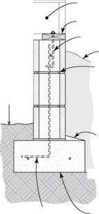
Подпись: 18 in. minimum between joists and dirt Подпись:Подпись: Vertical rebarCHOOSING A FOUNDATIONПодпись: Floor joist Mudsill Anchor bolt Backfill
Подпись: Slope the top of footing with mortar to shed water.Подпись:Concrete Block versus Poured Concrete Walls

If you have a large crew, like we do on most Habitat projects, it makes sense to build foundation walls with concrete block. All you need are a couple of experienced masons and enough volunteers to keep them supplied with blocks and mortar as they work their way around and up, course by course. A crawl-space foundation can be completed in just a couple of days. When building walls with concrete block, it’s easy to form beam pockets and openings for vents, doors, and windows. And by switching to a smaller block just below the planned grade level, you can create a ledge for brick veneer on the outside.

If you want a full basement and you don’t have a Habitat-size crew, poured concrete is the way to go. Most basement foundations are built with poured concrete walls that are formed and poured by foundation contractors.

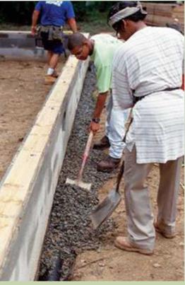
Подпись: ENSURING PROPER DRAINAGE We need water. We just don't need it in our basements or under our floors, causing dampness, mold, and rot. We may not be able to hold back the Mississippi when it floods, but we can control most of the rainwater that falls around our homes. Follow the guidelines below and you'll stand a good chance of keeping water on the out-side of your foundation. Подпись: Don't build on the lowest part of the lot. Seal all holes around the pipes that go through the concrete. Install perforated drainpipes at the bottom of the concrete foot-ings around the outside of the foundation (see the photo below). Coat the foundation walls with a suitable damp-proofing or wa-terproofing treatment. Check with builders in your area or the local building department to find out which foundation coatings are recommended.Tar coatings are inexpensive but not as effective as more recently developed waterproofing treatments. Compact loose fill as you backfill around the foundation, but be careful, because excessive compaction can damage masonry walls. Make sure that the finished grade (ground level) slopes away from the foundation. But remember that loose fill can settle. A finished grade that slopes away from the house may later slope toward the house should settling occur. ■ Use gutters and downspouts to manage high roof water run-off. Make sure you keep gutters unclogged and install down-spouts to direct water away from the house. ■ Get advice from your building department.The time to protect your house from water infiltration is while you are building. Fixing a leaky basement or a damp crawl space after the house has been built can be Подпись:CHOOSING A FOUNDATION

an ICF system, laying up foundation walls doesn’t demand back-breaking labor. Even so, many homebuilders still prefer to hire a foun­dation contractor to take on this phase of the construction project, and there’s nothing wrong with that choice. The important thing is to begin building on a base that’s level, square, and guaranteed to remain solid and stable for many years to come.

STEP 1 FORM AND POUR THE FOOTINGS

Thick, solid, and strong, footings evenly spread the weight of the house (and everything inside it) over a wide area, ensuring that the finished house does not settle. With some slab foundations, it’s possible to pour the footings and the slab at the same time. In other cases, the footings and the slab must be formed and poured separately. In many areas, a footing inspection by the building department is required; this must be done before the foundation walls are built.

Footings must be set on solid, undisturbed earth, not on fill dirt. Local soil conditions determine the depth and design of footings. In areas of the country where the ground freezes solid in the winter, footings must extend below the frost line, which can be 4 ft. or deeper in northern regions. This prevents the freeze-thaw cycle from moving the foundation, cracking it, and causing damage throughout the entire house. The building department in your area will know the footing depth that is required. They’ll also know about local soil conditions that may require a larger size footing or the use of rebar (steel reinforcing rod) in the footing.

Forms for footings

Footings are typically poured in temporary forms constructed from plywood or 2x lumber. Wood stakes and braces hold the forms in posi­tion. The top edges of the footing forms must be level, and the footings must be set to the dimen­sions specified on the plans. A ready-mix truck is called in to fill the footings with concrete. If
the site conditions make it difficult or impos­sible for the truck to get close to the forms, a mobile concrete pumper can be brought in to pump the concrete from the truck to the forms. Check with your building department about code requirements for footings. It also may be necessary to embed vertical rebar in the footings so that the upper part of the reinforcing rods can extend into the foundation wall.