Category WATER IN ROAD STRUCTURES

Hydrodynamic Types of Aquifers

л°0°аОгя^*«

) „О» "nOLr Од a

іе&9’"в?0да

Подпись:Подпись:Подпись:

Подпись: Confined Aquifer Подпись: Leaky Aquifer
Подпись: K
Подпись: K
Подпись: I K3
Подпись: :°oQ°^9.~.y4°c°Q> ^ o olpD О '<-> а о Oo О 4бО°° mnoo § K K2 Vpa^o 3flJoo о 04? o’oO § о 0°° СиЧ^оо 0 Q.a
Hydrodynamic Types of Aquifers
Подпись: K1 K1<< K2

Based on their ambient material, aquifers can be classified into three types, i. e. open, A confined aquifer is bounded both above and below by relatively impermeable materials or confining beds (such as clay or unfractured rock.) The confined wa­ter is under pressure thus a tube extended from the surface down into the aquifer would allow the water to rise inside the tube to a level above the top of the aquifer.

• An open aquifer is one without a confining bed above so it can be directly recharged by rainfall.

• A semi-confined aquifer is a confined aquifer where one of the confining beds is saturated material with low permeability which, thus, impedes the movements of the water.

Most road structures or road embankments can be considered open aquifers. Only under some special circumstances do they act as a semi-confined or confined aquifers.

For pavements and their relation to groundwater (from the geometrical point of view) perched-type aquifers are of importance. These aquifers are the consequence of some lower permeable lenses (e. g. clays) inside a permeable aquifer. As a conse­quence of a high coefficient of permeability of the aquifer material and favourable infiltration into the ground, water mounds appear above the lenses. These aquifers have no direct connections with lower lying groundwater. Usually they are very near the surface and may cause several problems for the construction and maintenance of the roads.

Relation Between Road and Groundwater

According to the literature, various definitions of groundwater exist. For some au­thors, groundwater is defined as water only in those pores that are completely

saturated, but for others a more general definition is acceptable with the ground­water being all the water below the ground surface either in the saturated or in the unsaturated part.

A geological medium containing groundwater is defined as an aquifer. Aquifers can be described as rock or soil (sediment) of high permeability that are able to store and transmit significant quantities of groundwater. In hydrogeological terms, the limit between an aquifer and less permeable geological media is frequently defined with a coefficient of permeability, K, of 10-6 m/s.

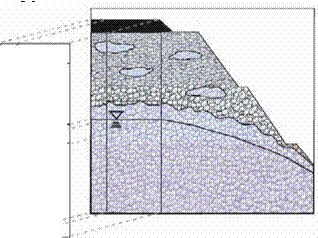
Figure 2.2 shows a schematic view of the regions of subsurface water in a pave­ment structure. The upper part represents the unsaturated or the vadose zone and the lower part represents the saturated or the phreatic zone. The groundwater table, defined as the surface where the water pressure is equal to the atmospheric pressure, separates them. The water content within the vadose zone is at saturation near its base while at its upper extent it is dependent on the characteristics of the soil. The vadose zone is divided into:

• a capillary zone. Above the groundwater table is the capillary zone or the cap­illary fringe because water is pulled upward from the water table by surface tension. The capability is linked to the pore size distribution of the material, the smaller the pores the greater the extent of the capillary rise. The thickness of the capillary fringe can vary from a few centimetres in coarse grained soils to a few metres in fine grained soils. The pores are saturated but the water pressure is less than atmospheric.

Relation Between Road and Groundwater

an intermediate vadose zone. The second sub-region of the vadose zone is the intermediate vadose zone where water is held by capillary forces. In sealed pavements in good conditions, the surface layer is relatively impermeable and the water held here should be relatively stable with water content at or near

field capacity (the remaining water content held by a soil after it has been allowed to drain freely), but through spring thaw or wet periods water could migrate inwards from the shoulders resulting in temporary higher water con­tents. In cracked pavements, on the other hand, water can move downward from the surface through the intermediate vadose zone to the capillary zone resulting, spatially, in periods of higher water content than the field capacity stipulates.

• a surface water zone. The layer closest to the surface is the surface water zone. Again, as for the intermediate vadose zone for sealed pavements in good condi­tions the water content should be relatively constant close to the field capacity or lower depending on atmospheric conditions. In cracked pavements on the other hand water can enter to the granular layer through cracks or other openings dur­ing periods of rainfalls and part of the layer may, therefore, include high water content or even become fully saturated.

In the unsaturated zone pore spaces are only partially filled with water and the direction of the groundwater flow is predominantly vertical. In the saturated zone, pores are completely filled with water and groundwater flow is nearly horizontal. The saturated aquifer zone is underlain by a low permeability basement stratum, known as the confining bed, which acts as a hydrogeological barrier. This is a nec­essary condition for the aquifer existence: without the barrier there would be no saturated zone.

Water Balance

For a better understanding of the qualitative and quantitative relationships between water and roads, the general interaction of road to water should first be established. The approach adopted here for this interaction analysis is by considering the water balance.

The relation between a road and water can be defined in system theory terms where input and output values are observed. Thus, the road and its pavement can be defined as a system into and out of which water flows. In normal conditions the input to the road pavement is represented by precipitation. Rainfall, or water due to thawing, infiltrates the pavement and flows through into the surrounding environ­ment. Reverse flow of surface or groundwater towards the pavement embankment is also possible.

The general water balance equation can be simply defined as

P = R – ETR + IR (2.1)

or

P = R – ETR + G + AS (2.2)

each term having units of volume/time/area [L/T] and where P represents the pre­cipitation, R is the surface runoff, ETR represents evapotranspiration, G is the deep percolation or the groundwater recharge, IR is the surface infiltration and AS is the water storage change (or the net volume flux, thus qout – qin) of the pavement structure or the embankment. When some external inflow, qext, to the system is present, the water balance equation is defined as

P + qext = R – ETR + G + AS (2.3)

The presence of external flow qext is particularly important when we want to define the water balance of a road that is interacting with its hinterland and, especially, remote water bodies.

The water balance of roads and embankments is complex, depending on the structure of the system and on the goals that have to be achieved with the water balance model. A conceptual water balance model of a pavement-embankment sys­tem is represented in Fig. 2.1.

BERM ROAD CUTTING

4————– M—————————————————————— ►

SLOPE SLOPE

•4————– ► 4———————————- ►

EMBANKEMENT TRENCH

4—————- ► 4——————- ►

Water Balance

Fig. 2.1 Conceptual model of water balance on pavement – embankment system. v = vertical, l = lateral, ca = carriageway, su = surfacing, rb = roadbase, sub = sub-base, sc = slope/cutting, t = trench, em = embankment and b = berm

The water balance of the road depends on the geometry of the road and on the course of the road through the land. The water balance differs for roads where the pavement is completely above the ground level from those roads where the pave­ment or the complete road is below surface of the ground or even in tunnels or covered galleries.

A detailed water balance model of the pavement addresses water flow for each pavement component. In Fig. 2.1, water balance components are defined for the car­riageway, surfacing, roadbase, sub-base and subgrade. Also reflected in this figure is the important influence on the water balance of the action of water flowing in the adjacent drainage ditches and on the slopes.

In general components of the water balance in the pavement can be divided into two general types: the vertical component (subscript v in Fig. 2.1) and the lateral component (subscript l in Fig. 2.1). Vertical components of the water balance rep­resent the recharge of, or loss from, the groundwater while the lateral components present the contribution to the total surface outflow from, or inflow to, the pavement system.

Water Flow Theory for Saturated and Unsaturated Pavement Material

SigurOur Erlingsson[3], Mihael Brencic and Andrew Dawson

Abstract This chapter describes the relation between road structures and water giving the general water balance equation for the pavement structure. Aquifers are briefly introduced. The pavement and its associated embankment are divided into the saturated zone and the unsaturated zone. Porous media are also described briefly together with their grain size distributions and fundamental properties related to wa­ter movements. A short summary of water flow theory for saturated and unsaturated soils is then presented, including relevant discussion of the soil water characteristic curve and permeability of unsaturated soils.

Keywords Roads ■ water flow ■ porous media ■ saturated ■ unsaturated ■ permeability ■ soil water characteristic curve

2.1 Introduction

During the planning, design, construction, operation and maintenance of roads, wa­ter can be an important environmental and constructional constraint that can signif­icantly influence the bearing capacity of the pavement, the safe operation of traffic and have a large influence on the operational costs of roads.

Due to their length, roads interact with various water phenomena. Interaction between roads and water phenomena can be conceptualized on the basis of the recharge area of the water that intercepts the road. These phenomena of water road interaction can be divided into three groups:

(i) the road’s own waters;

(ii) hinterland waters; and

(iii) remote waters.

The road’s own water is the runoff that arises as a consequence of precipitation falling onto the carriageway and onto the associated embankment. Hinterland waters come from the near-road environment (e. g. slopes from a cutting) and those which are flowing towards the road embankment. Remote waters have recharge areas far away from road but are crossing the line of the road (e. g. rivers, lakes, subterranean groundwater flow, etc.).

Terminology

Pavement sub-surface drainage lies at the boundary of several disciplines each hav­ing their own special terms and notations. The book does not avoid these but, rather, seeks to define them when they are used. To help readers, a “Glossary” is included (Annex C) as well as a list of terms in several languages (Annex B) and a list of symbols (Annex D).

1.5 Conclusion

Water and road construction do not make for a harmonious couple! While water is needed to allow efficient compaction of most of the earthworks and pavement layers and some moisture held in pores can act to develop strengthening suction due to capillarity effects, the overall picture is that water in the road and road sub-structure is undesirable. Water should, if possible, be kept out. If that is impossible (and it usually is impossible to achieve this) then efficient drains must be provided to con­vey the water away from the loaded areas. To bring about this happy condition, the road engineer has to understand about the response of pavement and geotechnical materials in the presence of water, about flow routes, about the drivers of water movement – climatic and hydrogeological – about the contaminants that can be moved in the water and about the regulatory framework in which he or she is obliged to operate. To successfully and economically deliver a well-behaved road is not easy to do. Therefore the following chapters aim to provide basic and more advanced information in all these areas. Not only do they aim to help the hard-pressed road engineer, but also to provide environmental engineers, hydrogeologists and others with a "language" in which to address the topics that have such an impact on every road user – on all of us!

Legal Considerations

1.12.1 National and Trans-National

The demands of legislation can greatly influence the design and management of a road in order to control its influence on the water environment. General legislation, such as European directives (e. g. the Water Framework Directive), define water pro­tection in a general manner with universal requirements that no pollutant input is allowed and that high cleanliness of water bodies should be established. However valid legislation at a national level, or even locally valid ordinances, can precisely define such requirements in terms of the level and manner of these protection mea­sures. The level of the protective prescriptions depends on the legal system. In some countries the valid legislation is very general repeating obligations from the Euro­pean directives and the proper implementation and then the functioning of protection measures are the responsibility of the road owner, operator and the designer. In some other cases, protection is very precisely defined by technical legislation that has been mandated centrally. In these kinds of document all the technical details can be found.

1.12.2 Local

During the development of a road scheme, existing hydrological and hydrogeolog­ical zones, crossed by road, are classified on the basis of legally existing water protection zones (e. g. drinking water source protection zones, Natura 2000 zones) and natural field conditions encountered. As a first step, desk studies are performed to define the demands and requirements for each section of the road consequent upon the legislation. Similar sections are then grouped together and field investi­gations undertaken to gather representative information on each group. Results of the field investigations are used to determine the specific level of water protection that is required. If the particular requirements defined in any existing protection ordinances are not as strict as those obtained as a consequence of the investiga­tions performed during the scheme development, technical protection measurements must be adopted to ensure that the water body is protected according to the natural conditions that have now been revealed. If prescribed demands in the ordinances are stricter than established by field investigations, the protection requirements are retained and usually the designer does not oppose them. The designer would need to be certain that every section within the group of sections being analysed was less susceptible to degradation. Even then, the time taken to get the water protection zones re-classified to a lower risk category will often be longer than the time taken to commence construction, negating the benefit that might otherwise accrue to the road scheme.

Among locally – and state-valid legislation, constraints to road construction and operation are usually defined in ordinances defining drinking water source protection zones. They are defined as requirements, prohibitions and restrictions and they can be grouped in the following way:

• restrictions on areas for construction of roads and manoeuvring areas;

• technical engineering requirements for the protection of groundwater (e. g. runoff collection / safety bunds / soakaways / pipe integrity);

• traffic speed restrictions, restrictions of certain traffic types;

• management control measures (e. g. cleanliness of drainage facilities, controlled disposal of plant cuttings, periodic water sampling, etc.);

• restrictions of transport of certain dangerous and harmful substances; and

• demands regarding the setting up of road signs in protected areas.

Climate and Climate Change

The ultimate reason for having drainage is because of rain! Therefore the drainage needs and solutions will be heavily influenced by the climate where the road is built. Broadly, climate may be divided by temperature and by rain/snowfall. Typically climatologists further differentiate on temperature variation across the year and on rainfall distribution. A very commonly used classification that takes this approach is that due to Koeppen (McKnight and Hess, 2000). This divides the world into 5 major zones, each with subdivisions:

• Tropical – subdivided into Rain Forest, Monsoon and Savannah;

• Dry – subdivided into Desert and Steppe;

• Temperate – subdivided into Mediterranean, Sub-tropical, Maritime and Maritime Sub-polar;

• Continental – subdivided into Hot Summer, Warm Summer and Sub-arctic; and

• Polar – subdivided into Tundra and Ice-cap. Alpine climates can be grouped here, too, although their climate results from elevation, not latitude.

The characteristics of each climate will have major effects on the water in the road and adjacent ground. In particular, where the potential for evaporation is

Climate and Climate Change

Fig. 1.12 Simplified climatic zone map of Europe. 1 – Temperate, maritime; 2 – Temperate, Mediterranean; 3 – Continental, warm summer; 4 – Dry, steppe; 5 – Temperate, sub-tropical; 6 – Alpine; 7 – Continental, sub-arctic; 8 – Polar, undifferentiated

significantly greater than rainfall, the effects of drainage may be less noticeable. However, this would need to be true throughout the year. Thus in tropical monsoon climates it may be true averaged over the year, but it is certainly not true during the wet season. It is at such a time that effective drainage may make the difference between survival of the road and its rapid deterioration.

Figure 1.12 shows a schematic division of Europe into the appropriate climatic zones.

In recent years the topic of climate change has become a consideration for almost everyone and road builders and operators are no exception. Temperature rise itself is unlikely to make a lot of difference to water in road structures in the warmer temperate areas, but in areas with seasonal freezing it could make a big difference. If the seasonal freeze period is reduced in length or lost or occurs repeatedly with intermittent thaw periods, then much longer periods of wet, non-frozen conditions (as currently experienced for shorter periods in the Autumn and Spring) can be expected, necessitating more stringent drainage requirements and causing much more frequent thaw-weakening problems. However, the shorter frozen period and the shallower penetration of the freezing front into the ground means that drainage trenches should more easily continue to operate year round.

Of likely importance to almost everyone is the increased rainfall that can be ex­pected. Warmer ocean temperatures will lead to higher amounts of water in the atmosphere and, thus, more rain and snow. Whether this water will come regularly or in a few, but more severe, storms is less certain and the answer may vary by lo­cality. The exact result may be difficult to predict, but the urgency for keeping water out of the pavement and associated highway earthworks can only increase. With greater runoff volumes anticipated, the need to provide positive drainage increases commensurately. Below ground it would be wise to anticipate greater volumetric flow rates of longer duration than previously experienced.

Drainage Systems

Drainage systems come in many shapes and forms (see Chapter 13) but they also share many common features – they are placed lower than the section of road or earthworks they are intended to drain and they comprise materials (and/or pipes) that

Подпись: Fig. 1.11 A gravel-lined swale with planted reeds to function as a soakaway. Reproduced by permission of VicUrban Note: Infiltration is encouraged by providing a porous surfacing.
Drainage Systems

are more permeable than the surrounding materials. Broadly, they may be classified as follows:

i) Horizontal (or sub-horizontal) drainage layers.

– When placed in, or more usually at the bottom of, some imported soil used for earthworks, these are termed blanket drains. Then they are used to isolate earthworks from underlying groundwaters, allowing any up-flowing water to be intercepted before it causes deterioration of earthworks and to catch water draining down from higher layers.

– Drainage layers may be provided only to carry small seepage flows con­sequent upon leakages in the otherwise impermeable pavement surface. Typically these are provided as an integral function of one of the road’s construction layers.

ii) Vertical, in soil, drainage trenches.

– Some are intended to provide drainage of earthworks structures. The amount of water to be carried (and, hence, the drain’s design) will depend on the
permeability of the ground to be drained and on the height of the natural water table.

– Pavement median or edge drains are usually installed at the edge of pave­ments, often extending down into the underlying natural soil or into the earthworks. Depending on the arrangements in force these may be expected to handle runoff water arriving from a pavement surface as well as from seepages carried to the pavement edge by a drainage layer (ib. above).

iii) Drains for structures. Drainage systems are usually installed behind constructed walls and bridge abutments so as to reduce the lateral water pressures on these structures. They are not considered in this book.

Conventional drains are provided by aggregate, with a low proportion of fine sizes, placed in or under the zone to be drained. When the natural ground, imported earth­works, or pavement layer that is to be drained is particularly fine graded, it may be necessary to place a filter layer between the natural soil and the drainage system element.

Nowadays, alternatives to aggregates are available to effect drainage. Except where large flows are expected, geosynthetic fin drains comprising an exterior “filter fabric” and an interior highly permeable core are generally accepted as suitable sub­stitutes for drainage ditches. They can be installed very rapidly and avoid expensive quarrying and associated transport of large volumes of dense materials. The “filter fabric” layer of the composite geosynthetic will normally be a felt-like layer around 1mm thick having a fairly small pore size. Although its pores will be too large to prevent every grain of the surrounding soil from going through into the interior core, they will halt somewhat larger particles that will, in their own turn, then allow layers of progressively finer particles to block the gaps between them. In this way a natural bridging layer will develop such that an effective filter zone will be catalysed by the “filter fabric”.

Where low flows are expected, the water may be carried within the drainage medium (stone or geosynthetic), but where moderate or high flows can be antici­pated it becomes necessary to install a pipe at the bottom of the trench or fin. This has to be permeable in some way (slotted, holed or integral with the fin drain) so that the water collected by the drain may be fed to the pipe and thereby carried away.

Runoff

Runoff derives, principally, from rainfall falling on the pavement and surround­ing ground. Although surface water drainage falls outside the scope of this book, runoff becomes of interest as some soaks in through cracks or through pervious surfacings. The proportion soaking-in will vary depending on the rainfall pattern, road surface quality and the permeability of the road’s margins and surrounding earthworks. At the margins the water should be routed into a drainage system. If a positive drainage system is provided then kerbs or gullies will intercept the surface flow and feed it to gulley pots and/or a piped drainage system. From there, water may be fed to some disposal system – this may be a soakaway to the ground or it may be to a surface water course. Normally road runoff will be given some treat­ment before it is disposed. Treatment will usually include solids settlement and oil separation.

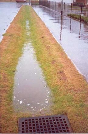
In areas where land is available, the runoff may be fed into an open, vegetated, lateral ditch known as a swale (see Figs. 1.10 and 1.11). These can form part of “SUDS” (Sustainable Urban Drainage Systems). Together with filter strips, infil­tration trenches and basins, porous pavement surfaces, constructed wetlands (e. g. reedbeds) and detention and retention ponds, they tend to act as natural attenua­tors of contaminants that will be sorbed into the ditch lining and taken up into the vegetation which, periodically, can be cut and removed. They also act as sediment traps, removing suspended solids. Excess water that does eventually arrive at a sur­face water course, or that soaks down to the water table, will usually be relatively

Подпись: Fig. 1.10 A well designed and maintained roadside swale operating correctly in heavy rain. Reproduced by permission of Chris Jefferies Note: The grass-lined swale has a drainage grill set 300 mm above the base to encourage storage and infiltration of water into the ground.
Runoff

clean due to the natural attenuation processes encountered en route. However, this means of treating and disposing of water that potentially contains contaminants can­not be used unthinkingly. There are many natural environments that are “highly vul­nerable”. High vulnerability exists when a near-highway environment can be easily polluted by runoff water (for example, where seeping water provides drinking water or sustains a quality ecosystem). The rare, but critical, occurrence of an accidental spillage, e. g. following a tanker crash, can cause acute effects to down-gradient waters.

The Effect of Temperature

Pore suctions have the effect of “pulling” the saturated zone nearer the ground surface than it would otherwise have been from where evaporation becomes pos­sible. When evaporation is significant then upward water flow takes place to re­place the water being evaporated. Evapotranspiration by vegetation also introduces an upward water flow towards roots in a similar manner. In hot climates, evap­oration can lead to upward moving water tens of metres above the phreatic sur­face and it can also lead to salts being lifted to the surface where they precipitate out in the soil pores forming calcretes and silcretes (Sabkha soils are an example of this).

Another cause of suction is seasonal ground freezing in high latitudes or at high altitudes. For reasons explained in Chapter 4, considerable ice wedges may form at the boundary between freezing caused by cold road surface temperatures and underlying non-frozen soils (Fig. 1.8). By this means, soils may heave by hundreds of millimetres in a winter season.

In spring, this ice melts, but the warmth comes from the surface so that the ice nearest the surface melts first. As there is still ice below it (and probably in the mar­gin of the roads where the surrounding ground is covered by snow and ice cleared from the road pavement), the water from the melted ice has nowhere to drain and extremely weak conditions can result (Fig. 1.9).

Подпись: Fig. 1.8 Ice lenses in a silty subgrade, Kuorevesi, Finland, Spring 2003. Reproduced by permission of N. Vuorimies
The Effect of Temperature

Just as evaporation, evapotranspiration and freezing are non-constant processes drawing water up from the groundwater zone, so rainfall is an intermittent supplier of water at, or near (via drains or soakaways) the surface causing a downward flow. A small amount of rain very rapidly cancels a high suction (thus suddenly reducing the effective stress and the frictional strength of a soil – see Section 1.4.3). It is partly for this reason that wet weather is so often associated with occurrence of slope distress in earthworks and in deformation of pavements.

The Effect of Temperature

Fig. 1.9 Thin asphaltic surfacing of a road lifted by traffic-induced water pressure during spring-thaw in Northern-Karelia, Finland. Reproduced by permission of M. Leppanen