Bath with frills

Perhaps, all technical development known for today concerning comfortable аква massage in house criteria, held in this subject, about Bath with frills
which conversation in given announcements will go. The brand new model of a hydromassage bath of Sharp Extra from the Italian brand of Jacuzzi known for the whole world possesses incontestable pluses and advantages Continue reading

Exhibition with a bias in AQUA

At first September (04.09 – 07.09) the current year in Atakent exhibition complex to Almaty (Kazakhstan) the largest will pass in Central Asia kazhdogodny the specialist the Aqua-Therm Almaty exhibition.

The main sections of the Aqua-Therm Almaty 2012 exhibition directed on a certain subject clasp a big range of products and the definitions applied Continue reading

On though what taste

On though what taste
What requirements are usually shown to kitchen mixers? At first it, naturally, convenience, functionality and reliability. But not on the last place there is also a nice external shape, after all in kitchen we use the mixer in times more often, than in a bathroom, and it is even more pleasant to see fine forms, if something unclear.

The brand Continue reading

Types of mixers

Types of mixers
Usually, in the apartment or the personal house we are established mixers of the 2nd types (on ordering) – for a sink or a sink and for a bath.

The mixer for a sink has only one having given vent for water – bottom or top. Such mixers are created for washing of ware and hands. Mixers for a bath have more difficult configuration and the toggle-switch Continue reading

And again about pumps

The title of this company being the leading producer of the pump equipment in the world, povsevremenno at all very famous. It is logical, after all in our news information on the next novelties, and similar "fertility" often slips it is possible to envy only.

Probably, you already guessed that now speech again will go about Grundfos Continue reading

DRY-SET EXTERIOR STEPS

Brick


DRY-SET EXTERIOR STEPSDRY-SET EXTERIOR STEPSDRY-SET EXTERIOR STEPSDRY-SET EXTERIOR STEPSDRY-SET EXTERIOR STEPSDRY-SET EXTERIOR STEPSDRY-SET EXTERIOR STEPSDRY-SET EXTERIOR STEPS

Подпись: 4 x 4 PRESSURE-TREATED RISER ATTACHED AT ENDS TO CONCRETE OR MASONRY WALL OR TO PRESSURE-TREATED STRINGER.DRY-SET EXTERIOR STEPSПодпись:Подпись:DRY-SET EXTERIOR STEPSПодпись: ,вО О О О ОПодпись: 0Рл° 0 0 О'о. • л п о о о ОПодпись: • •д-g . . ** a . о o°o Ooj> /  . п л « л A Подпись: ° о о о Oo 00 0°0 oOo 0 ,0 О о 0°д0 ° “ ° 0 DRY-SET EXTERIOR STEPSПодпись: ]Подпись: 'о’оРлОоО 0ovo ,o"t°(0»0 ..o' 0 о °o0 oo

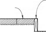
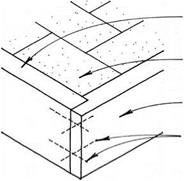
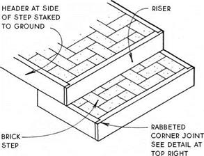
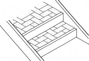
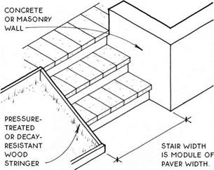
Dry-set concrete paver steps, like dry-set brick steps, are supported on a bed of compacted gravel on the ground and are laid dry without concrete or mortar. Because of their size, large pavers like the ones shown here are more stable than bricks. For this reason, paver stairs may be constructed without containment at the riser; some paver stairs are even constructed without

containment at the sides.

16-IN.

CONCRETE

PAVER

paver projects over riser about 1 IN.

-cl

Щщт

compacted rock base or self-compacting pea gravel

Most paver stairs are contained at the sides with walls or stringers, as shown below.

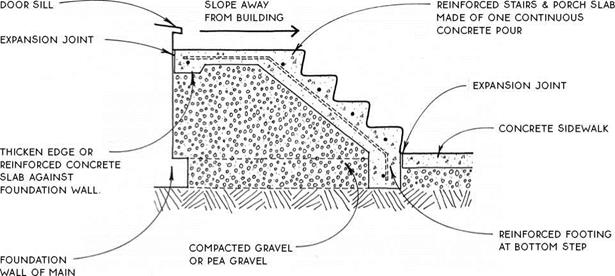
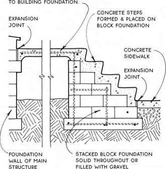
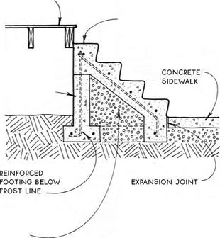
Concrete steps are durable and can be reasonably inexpensive, especially if they are built along with other concrete work. They should be adequately supported on a foundation and should be reinforced. Handrails or handrail supports may be cast into the steps or into the walks, porches, or terraces adjacent to them. The steps may be covered with a masonry or other veneer.

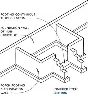
The main problem with concrete steps is that they are difficult to repair if anything should go wrong with them. The usual problem is settling due to the extreme weight of the steps themselves and to the fact that they are often constructed on fill. The safest way to avoid settling is to provide for the porch and steps a footing that is below the frost line, with a foundation wall above. This footing and foundation wall system may be an integral part of the foundation of the main structure (see the detail below), or it may be independent of the main structure with an expansion joint adjacent to the main structure that will allow the porch to move slightly without cracking (see 225A & B). Alternatively, concrete steps may be built independent of the main structure and adjacent to a wood porch (see 225C). All methods are expensive but will avoid costly maintenance in the long run.

For areas where building on backfill cannot be avoided, a wood porch with a lightweight wood stair that can be easily releveled is the most practical (see 222).

DRY-SET EXTERIOR STEPS

DRY-SET EXTERIOR STEPSПодпись:Paver stairs may also be contained at all edges like brick stairs with 2x risers and side headers (see 223).
DRY-SET EXTERIOR STEPS

Concrete Pavers

NOTE

ELEMENTS OF THE DETAiLS ON THiS PAGE MAY BE COMBiNED iN VARiOUS WAYS TO MEET THE NEEDS OF SPECiFiC SiTUATiONS.

DRY-SET EXTERIOR STEPS

structure

ДЛ CONCRETE STEPS ON GRAVEL

-__ ‘ At Concrete Porch

REINFORcED concrete pORcH spans from step FOuNDATION


wood porch SEE 52-60


REiNFORcED concrete steps


STEM Wall

including

SiDES IF

required


NOTE

coordinate WOOD porch SKIRT WITH EDGE OF cONcRETE STAIR.


compacted gravel OR pea gravel


DRY-SET EXTERIOR STEPSDRY-SET EXTERIOR STEPS

Подпись: CONCRETE STEPS ON BLOCK At Concrete Porch CONCRETE STEPS AT WOOD PORCH

On Block or Gravel

legend


CONTINUOUS STRUCTURAL FRAMING MEMBER


CONCRETE


DRY-SET EXTERIOR STEPS

BLOCKING (NOT CONTINUOUS)


GRAVEL FILL


oo^o. Я’О


I


WOOD FINISH MATERIAL


UNDISTURBED SOIL


і


PLYWOOD OR OTHER STRUCTURAL PANEL


SAND FILL


STUCCO OR GYPSUM WALL BOARD (G. W.B.)


RIGID INSULATION


MATERIAL BURIED IN ANOTHER MATERIAL.

E. G., REBAR IN CONCRETE


ВАТТ INSULATION


MASONRY-BRICK OR CONCRETE BLOCK


FUTURE

CONSTRUCTION


DRY-SET EXTERIOR STEPSDRY-SET EXTERIOR STEPSDRY-SET EXTERIOR STEPSDRY-SET EXTERIOR STEPSDRY-SET EXTERIOR STEPSDRY-SET EXTERIOR STEPSDRY-SET EXTERIOR STEPS

PROBLEMS WITH A LEACH FIELD

Problems with a leach field are uncommon among new installations. Unless the field was poorly designed or installed improperly, there is very little rea­son why it should fail. However, extremely wet ground conditions, due to heavy or constant rains, could force a field to become saturated. If the field saturates with ground water, it cannot accept the effluent from a septic tank. This, in turn, causes backups in houses. When this is the case, the person who created the septic design should be looked to in terms of fault.

Older Fields

Older fields sometimes clog up and fail. Some drain fields become clogged with solids. Financially, this is a devastating discovery. A clogged field has to be dug up and replaced. Much of the crushed stone might be salvageable, but the pipe, the excavation, and whatever new stone is needed can cost thou­sands of dollars. The reasons for a problem of this nature are either a poor de­sign, bad workmanship, or abuse.

If the septic tank installed for a system is too small, solids are likely to en­ter the drain field. An undersized tank could be the result of a poor septic de­sign, or it could come about as a family grows and adds onto their home.

A tank that is adequate for two people may not be able to keep up with the us­age seen when four people are involved. Unfortunately, finding out that a tank is too small often doesn’t happen until the damage has already been done.

Подпись:Why would a small septic tank create problems with a drain field? Septic tanks accept solids and liquids. Ideally, only liquids should leave the septic tank and enter the leach field. Bacterial action occurs in a septic tank to break down solids. if a tank is too small, there is not adequate time for the breakdown of solids to occur. increased loads on a small tank can force solids down into the drain field. After this happens for a while, the solids plug up the drainage areas in the field. This is when digging and replace­ment is needed.

in terms of a septic tank, a pipe with a fast grade can cause solids to be stirred up and sent down the outlet pipe. When a four-inch wall of water dumps into a sep­tic tank at a rapid rate, it can create quite a ripple effect. The force of the water might generate enough stir to float solids that should be sinking. If these solids find their way into a leach field, clogging is likely.

We talked a little bit about garbage disposers earlier. When a disposer is used in conjunction with a septic system, there are more solids involved that what would exist without a disposer. This, where code allows, calls for a larger septic tank. Due to the increase in solids, a larger tank is needed for satisfac­tory operation and a reduction in the risk of a clogged field. I remind you again, some plumbing codes prohibit the use of garbage disposers where a septic system is present.

other causes for field failures can be related to collapsed piping. This is not common with today’s modern materials, but it is a fact of life with some old drain fields. Heavy vehicular traffic over a field can compress it and cause the field to fail. This is true even of modern fields. Saturation of a drain field will cause it to fail. This could be the result of seasonal water tables or pro­longed use of a field that is giving up the ghost.

Septic tanks should have the solids pumped out of them on a regular ba­sis. For a normal residential system, pumping once every two years should be adequate. Septic professionals can measure sludge levels and determine if pumping is needed. Failure to pump a system routinely can result in a build­up of solids that may invade and clog a leach field.

Normally, septic systems are not considered to be a plumber’s problem. Once you establish that a customer’s grief is coming from a failed septic sys­tem, you should be off the hook. Advise your customers to call septic profes­sionals and go onto your next service call; you’ve earned your money.

This page intentionally left blank.

Подпись: NATIONAL RAINFALL STATISTICS

ational rainfall statistics are needed for computing the requirements of storm water systems. The expected rainfall rates are needed to fig­ure out systems for roof drains, storm sewers, and similar methods of controlling storm water drainage. Fortunately, the rainfall rates for major cities are listed in this chapter. Similar information can often be found in plumbing codebooks. You will also find rain maps in this chapter and some codebooks. You can’t accomplish much with only the rainfall rates. Consider the following information as reference material that you can use at anytime to compute the needs for controlling storm water. (Figs. A1.1 to A1.5)

309

PROBLEMS WITH A LEACH FIELD

PROBLEMS WITH A LEACH FIELD

Virginia

Bristol

2.7

Charlottesville

2.8

Lynchburg

3.2

Norfolk

3.4

Richmond

Washington

3.3

Omak

1.1

Port Angeles

1.1

Seattle

1.4

Spokane

1.0

Yakima

West Virginia

1.1

Charleston

2.8

Morgantown

Wisconsin

2.7

Ashland

2.5

Eau Claire

2.9

Green Bay

2.6

La Crosse

3.1

Madison

3.0

Milwaukee

Wyoming

3.0

Cheyenne

2.2

Fort Bridger

1.3

Lander

1.5

New Castle

2.5

Sheridan

1.7

Yellowstone Park

1.4


FIGURE A1.1 ■ (Continued) Rainfall rates.


PROBLEMS WITH A LEACH FIELD

PROBLEMS WITH A LEACH FIELD

OJ

GO


Подпись: PLUMBER'S AND PIPE FITTER'S CALCULATIONS MANUAL

PROBLEMS WITH A LEACH FIELD

[Birmingham, Alabama


[Anniston, Alabama


[Montgomery, Alabama


J^oents, AruonT


[Bentonville, Arkansas


‘Fort Smith, Arkansas


Mt. Tamalpais. California


Eureka, alifornia


.Fresno, California,


•Los Angeies, California


ft Reyes, California


■Red Sluft, Calilorni


.Sacramento, California,


.Sen Lois Obispo, California


‘San7rancfsco, California


San Jose, California


[Denver,


Minutes Duration


PROBLEMS WITH A LEACH FIELD

PROBLEMS WITH A LEACH FIELD

FIGURE A1.5 ■ Rainfall intensity-duration-frequency charts. (Courtesy of McGraw-Hill)

Grand Junction, Colorado1


-^Pueblo, Colorado


•Wagon Wheel Gap, Colorado


^Hartford, Connecticut


Jacksonville, Florida


1W ashing ton r D. C.


; Apalachicola, Florida


New Haven, Connecticut’


;Sand Key, Florida;


:Key West Florida


Pensacola, Florida


Macon, Georgia-


Augusta, Georgia


■Savannah, Georgia-


.Lewiston, Idaho,


■Thomasulfa, Georgia*


:Chicago, minors


.Pocatello, Idaho


Peoria, Illinois


■Evansville, Indiana


‘indlanapolis. Tndiana


;Fort Wayne, Indiana


ICharles City, Iowa’


;Des Moines, Iowa


davenport Iowa


; Keokuk, Iowa;


.Concordia, Kansas


Minutes Duration


PROBLEMS WITH A LEACH FIELD

PROBLEMS WITH A LEACH FIELD

Wichita. Kansas


«Podge City, Kansas’


■Topefcs. Kansas


Shreveport, Louisiana


^Lexington, Kentucky;


і Louisville, Kentucky


New Orleans, Louisiana


•Portland, Maine


.Baltimore, Maryland


■Boston, Massachusetts


‘Eastport, Maine


PROBLEMS WITH A LEACH FIELD

■Detroit Michigan


-East Lansing, Michigan


;Alpena, Michigan;


•Escanaba, Michigan


■Grand Haven, Michigan


•Grand Rapids, Michigan


‘Houghton,


|Sault Ste. Marie, Michigan


Duluth, Minnesota.


[Marquette, Michigan


•Moorhead, Minnesota


[Minneapolis, Minnesota


]St. Paul,.Minnesota1


[Meridian, Mississippi


[Colombia, Missouri


Hannibal, Missouri


•Kansas City, Missouri


Vicksburg, Mississippi;


Missouri


‘яїоак.’Missouri


Minutes Duration


PROBLEMS WITH A LEACH FIELD

PROBLEMS WITH A LEACH FIELD

Miss dull, Montana


Каи spell, Montana


;Omaha, Nehraska!


;Lincoln, Nebraska


■North Platt», Nebraska


Atlantic City, New Jersey


.Winnenuicci, Nevada


■Concord, New Hampshire]


T re ntonNewTersoy


■SmghamtQ. n, New York


Fe, New Mexico


Oswego, ftewYoTk


.Rochester, New’York


-Asheville, North Caroline-


^Charlotte, North


■Raleigh, North Carolina


filming ton, North


Greensboro, North Carolina^


;&evils Lake, NorthDskota"


Bismarck, Norl


PROBLEMS WITH A LEACH FIELD

PROBLEMS WITH A LEACH FIELD

PROBLEMS WITH A LEACH FIELD

‘Cleveland, QbfO


■ Sandusky. Ohio


‘Columbus, Ohio


.Portland, Oregon


PROBLEMS WITH A LEACH FIELD

■Roseburg, Oregon


Erie, Pennsylvania


IHamsburs


Philadelphia, Pennsylvania


Шоск island Rhode Stand


Pennsylvania


Reading, Pennsylvania


[Scranton, Pennsylvania^


Greenville,’South СаюІівГ


■Columbia, South Carolina


‘Providenot, Rhode stand


Charleston South Carolina-


10


[Pierre, South D kota


■Yankton, Sou h Dakota’


Rapid City, South Dakota


[Chattanooga, Tennessee


■ Nashville, Tennessee1


•Knoxville Tennessee


; Mem phis, Tennessee;


■Amarillo, Texas-


[Brownsville, Texes


■ Corpus CbristJ, Texas –


Mmutes Duration


PROBLEMS WITH A LEACH FIELD

PROBLEMS WITH A LEACH FIELD

Fort Worth, Texas


.Galveston, Texas


Houston, Texas,


Palestine, Texas


San Antonio, Texas


Port Arthur, Texas


■Burlington, Vermont1


Northtield, Vermont –


Lynchburg. Virginia


Richmond. Virginia


-Wytheville, Virginia-


Seattle, Washington


.North Head, Washington.


/ort Angeles, Washington.


.Spokane, Washington.


Tacoma, Washington1


Walla Walla, Washington.


Yakima, Washington


;Green Bay, Wisconsin-


■la Crosse, Wisconsin’


•Madison, Wisconsin


Parkersburg, West Virginia


[f-M. ii wau’k ее, Wi7;


■ Sheridan. Wyoming’


-Cheyenne, Wyoming-


■Lander, Wyoming-


;San Juan, Puerto Rico;


-Honolulu, Hawaii


■Fairbanks. Alaska


Juneau, Alaska


Minutes Duration


PROBLEMS WITH A LEACH FIELD

Water Disposal

[1] Annex C contains a Glossary of terms that may be unfamiliar to some readers.

[2] The terms permeability and hydraulic conductivity are both used to mean the ease with which water travels through saturated, porous media. In this book the term permeability is used pref­erentially. In particular the ‘coefficient of hydraulic conductivity’ and the term ‘coefficient of permeability’ are identical and given the symbol K.

[3] Co-ordinating Author:

23 S. Erlingsson

Haskoli Islands/University of Iceland, Iceland & Statens vag-och transportforskningsinstitut/ Swedish National Road and Transport Institute, Sweden e-mail: sigger@hi. is

A. R. Dawson (ed.), Water in Road Structures, DOI 10.1007/978-1-4020-8562-8_2, © Springer Science+Business Media B. V. 2009

[4] Co-ordinating Author:

23 S. Erlingsson

Haskoli Islands/University of Iceland, Iceland & Statens vag-och transportforskningsinstitut/ Swedish National Road and Transport Institute, Sweden e-mail: sigger@hi. is

A. R. Dawson (ed.), Water in Road Structures, DOI 10.1007/978-1-4020-8562-8_3, © Springer Science+Business Media B. V. 2009

[5] Reference should be made to Chapter 10, Section 10.3, and to Eqs. 10.1-10.4 for an explanation of FWD assessment and of BCI and SCI.

[6] Co-ordinating Author:

23 A. Hermansson

Vag-och Transportforskningsinstitut / Swedish Road and Traffic Institute (VTI) e-mail: ake. hermansson@vti. se

A. R. Dawson (ed.), Water in Road Structures, DOI 10.1007/978-1-4020-8562-8_4, 69

© Springer Science+Business Media B. V. 2009

[7] Co-ordinating Author:

E3 A. R. Dawson

University of Nottingham, Nottingham, UK e-mail: andrew. dawson@nottingham. ac. uk

A. R. Dawson (ed.), Water in Road Structures, DOI 10.1007/978-1-4020-8562-8.5, © Springer Science+Business Media B. V. 2009

[8] In British English, bitumen refers to the binder in an asphaltic material whereas in American En­glish the term asphalt-cement is normally used, or simply ‘asphalt’. In this book the term bitumen is used to describe the binder and the word asphalt (which in British English refers to the whole mixture) is not used alone, to avoid confusion.

[9] AAD is one of the core SHRP bitumen binders

[10] PG = Penetration Grade

[11] 0

0 10 20 30 40 50 60

Months since opening

[12] Co-ordinating Authors:

ISIL. Folkeson

Statens vag – och transportforskningsinstitut/Swedish National Road and Transport Research Institute (VTI)

e-mail: lennart. folkeson@vti. se IE3 T. B^kken

Norsk Institutt for Vannforskning/Norwegian Institute for Water Research (NIVA) e-mail: torleif. baekken@niva. no

A. R. Dawson (ed.), Water in Road Structures, DOI 10.1007/978-1-4020-8562-8_6, © Springer Science+Business Media B. V. 2009

[13] The use of the word ‘particle’ here is to differentiate the type of chemical component being exchanged from protons and electrons which are much smaller. It is not used to indicate a solid and visible particle (e. g. of sand) as elsewhere in the book.

[14] See previous footnote

[15] Alphanumeric codes are as used in Fig. 6.5

* Co-ordinating Authors:

23 T. Leitao

Laboratorio Nacional de Engenharia Civil / National Laboratory for Civil Engineering (LNEC), Portugal

e-mail: tleitao@lnec. pt

[17] A. R. Dawson

University of Nottingham, Nottingham, UK e-mail: andrew. dawson@nottingham. ac. uk

A. R. Dawson (ed.), Water in Road Structures, DOI 10.1007/978-1-4020-8562-8_7, © Springer Science+Business Media B. V. 2009

[18] for runoff: FHWA (1987, 1996), Hamilton et al. (1991), Hvitved-Jacobsen & Yousef (1991), and Wanielsita & Yousef (1993);

• for surface water: Ruttner (1952), Krajca (1989), Environment Agency (1998);

• for groundwater, soil water and soil: Barcelona et al. (1985), Canter et al. (1987), Nielsen (1991), Clark (1993) and Boulding (1995).

[19] extract metals of the exchangeable and acid extractable fraction (using CH3 COOH 0.11 M);

• extract metals of the reducible fraction (using NH2OH, HCl 0.1 M; pH 2);

[20] Co-ordinating Author:

R. Charlier

University of Liege, Belgium e-mail: robert. charlier@ulg. ac. be

A. R. Dawson (ed.), Water in Road Structures, DOI 10.1007/978-1-4020-8562-8_8, © Springer Science+Business Media B. V. 2009

[21] water entered through the joints between the slabs;

• the water softened the supporting layers allowing the slab to deflect under traffic;

• the increased dynamic movement of the slab when trafficked caused a “pumping” action by which water was rapidly displaced from the pores in the supporting material;

[22] Co-ordinating Author:

E3 L. Laloui

Ecole Polytechnique Federal de Lausanne, Swiss Federal Institute of Technology, Switzerland email: lyesse. laloui@epfl. ch

A. R. Dawson (ed.), Water in Road Structures, DOI 10.1007/978-1-4020-8562-8_9, © Springer Science+Business Media B. V. 2009

[23] An elastic (resilient) model with a modulus depending on the stress and suction level. A rigorous development should lead to a hyper-elastic model. Such a model would be sufficient for routine pavement design. It seems not to exist at present.

• Improving the available models, such as the Chazallon-Hornych, the Suiker or the Mayoraz models, implies the addition of yield/potential surfaces and a de­pendency on the suction. The elastic stress space, lying inside the yield surface would be higher for high suction; wetting would reduce the elastic domain and then increases the irreversible strains that occur under each load cycle.

[24] Co-ordinating Author:

EE3 C. Cekerevac Stucky SA, Switzerland e-mail: ccekerevac@stucky. ch

A. R. Dawson (ed.), Water in Road Structures, DOI 10.1007/978-1-4020-8562-8.10, © Springer Science+Business Media B. V. 2009

[25] Co-ordinating Author:

R. Charlier

University of Liege, Belgium e-mail: robert. charlier@ulg. ac. be

A. R. Dawson (ed.), Water in Road Structures, DOI 10.1007/978-1-4020-8562-8_11, © Springer Science+Business Media B. V. 2009

[26] This concerns Galerkin’s approximation. For advection dominated problems, other weighting functions have to be used.

[27] Co-ordinating Author:

IE3 M. Brencic

Geoloski zavod Slovenije/Geological Survey of Slovenia e-mail: mihael. brencic@geo-zs. si

A. R. Dawson (ed.), Water in Road Structures, DOI 10.1007/978-1-4020-8562-8_12, © Springer Science+Business Media B. V. 2009

[28] Co-ordinating Author:

23 J. S. Faisca

Estradas de Portugal/Roads of Portugal, Portugal e-mail: jose. faisca@estradasdeportugal. pt

A. R. Dawson (ed.), Water in Road Structures, DOI 10.1007/978-1-4020-8562-8_13, 299

© Springer Science+Business Media B. V. 2009

[29] This can be said because, under vertical flow, there is a hydraulic gradient of1 so the Darcy flow velocity has the same numeric value as the coefficient of permeability.

[30] Typically soakaways should be able to cope with water flow from a two-year return period ‘high’ (or other agreed return period).

[31] deep GBR on side slopes – where the GBR is installed under the drainage col­lection system and covers the entire slope as well as the ditch area (Fig. 13.35);

[32] Standard terminology has been adopted for pavement layers in EN standards and these are given here. In parentheses are given the traditional terms

This section provides general designs of the final elements the water runs through before going to existing water bodies.

B.6.1 Retention Ponds/Кексіves стггукрat^ct^s

Language

Item no.

1

2

3

4

5

6

7

English

retention pond

inlet

throttle pipe

outlet

minimum level

operating depth

overflow pipe

German

Regenruckhaltebecken

Zulauf

Drosselrohr

Ablauf

tiefstes Absenkziel

Stauhohe

Uberlaufrohr

Spanish

cubeta de retencion

entrada

tuberia de regulacion de nivel

desagiie

nivel minimo

profundidad de trabajo

tuberia de desbordamiento

French

bassin de retention

arrivee

valve pointeau

sortie

niveau le plus bas

niveau de fonctionnement

tuyau de trop plein

Italian

bacino di ritenzione

ingresso

condotta di strozzamento

uscita

livello minimo

profondita’ di esercizio

condotta di sfioro

Greek

Лєкау^ on^KpaT^CT^s

Eiao8os

ХшХт) vas a^oaTpct 77ia^s

E^o8os

EX(ixiCTTo ern-^eSo

Ba0os XeiTonp^ias

XwXt) vas n^epxeiXia^s

B.6.2 Soakaways/Аушуоі а^аушуі]s o^Ppiwv

Language

Item no.

1

2

3

4

English

porous wall

void

access cover

inlet pipe

German

durchlassige Wand

Hohlraum

Schachtabdeckung

Zulaufrohr

Spanish

pared porosa

hueco

recinto cerrado de acceso

tuberia de entrada

French

mur poreux

vide

acces superieur

conduite d’arrivee

Italian

muro poroso

vuoto

copertura di accesso

condotta d’ingresso

Greek

Дютсерата touxco|хата

Ker>o

KaXv^^a етсткеф^?

SwXiqvas еишэ8ov

Polish

sciana porowata

komora

wlaz

rura wlotowa

Portuguese

Parede porosa

Vazios

Tampa de acesso

Colector de entrada

Serbian

Porozni zid

Otvor sahta

Poklopac sahta

Dovodna cev

Slovenian

perforirana stena

jasek

pokrov jaska

dovodna cev

Danish

vandgennemtrangelige sider

hulrum

d^ksel

indlobsrar

CARPETING STAIRS

If possible, use a single strip of carpet on stairs, eliminating seams. Stair padding can be many pieces because it will be covered by carpet. For the best-looking job, carpet pile on treads should slant toward you as you ascend the stairs. On ris­ers, the pile should, therefore, point down. If you use several pieces of carpet on the stairs, for durability and appearance, carpet seams should always meet in riser-tread joints.

Estimating and ordering. First, determine the width of the runner. On closed stairs (which have walls on both sides), carpeting usually runs from wall to wall. On open stairs (with balusters on one or both sides), carpeting should run to the base of the balusters. In either case, each side of the car­pet should be tucked under 1J4 in. to hide the cut edge and prevent its unraveling. Thus measure the width of the stairs and add 2/2 in. to that width. So if your stairs are 36 in. wide, you’ll be able to cut only three runners from each 12-ft. width of carpeting, allowing for tuck-unders and waste.

To determine the overall length of the stair runner, measure from the edge of the tread nos­ing to the riser, and from there up the riser to the nosing of the step above. Add 1 in. to this meas­urement to accommodate the padding over the step and multiply this by the number of steps. Add 6 in. to that total for adjustments at the top and bottom of the stairs.

That’s a formula for straight-run stairs. If yours have bends and turns, create a paper tem­plate for each step that turns. Each template should cover a tread and the riser below. As noted above, add 1 in. for the distance the padding sticks out around the nosing. However, some old hands at laying carpet feel that stairs should be covered only with continuous pieces, with extra carpet tucked behind riser sections.

Installing carpet on stairs. Nail tackless strips on the stair risers and stair treads so that tack points on risers point down, and those on the treads point in, toward the risers. The tackless strip on each tread should be about 3з8 in. away from the riser, so there’s a gap to tuck the carpet into. The tackless strip on each riser should be about 1 in. above the tread. Tackless strips should be 2h in. shorter than the width of carpet with tucked-under edges. That is, each edge is 1% in. wide and does not attach to the tackless strip.

So the strips must stop short by that amount. Instead, tucked-under edges of carpet will be tacked with a 134-in. tack on each side, driven into the riser-tread joint.

Padding pieces are as wide as the tackless strips are long. Butt the padding to the edge of the strips. To keep the pad from being seen from the open side of a stairway, cut the riser portion of the padding at an angle, as shown below left. Staple the padding every 3 in. to 4 in. To tuck the carpet edges, snap chalklines on the backing,

134 in. from the edges. Use an awl (not a utility knife) to score lightly along the lines, fold the edges under, and then weight them down for a few minutes to establish a slight crease.

Secure the bottom of the stair runner first, overlapping the carpet about 34 in. onto the floor; push the carpet into the tackless strip at the base of the first riser. (The tackless strip on the first riser should be!4 in. above the floor.) Press the carpet onto the strip points with a stair tool. Tack the bottom of the rolled edges onto the riser with a 134-in. tack at each end. Then pack the extra end of the carpet into the ^-in. gap between the tack­less strip and the floor.

To cover the first step, stretch the carpet with a knee-kicker, starting at the center of the tread. As you push the knee-kicker, use a stair tool to tamp the carpet into the riser-tread joint. Work out from the center of the step, until the carpet is attached to tackless strips along the entire joint. At the end of each side, secure the tucked-under edge with a single 1 ^-in. tack. Continue up the stairs, using the knee-kicker and stair tool. If the width of the carpet varies (sometimes a tucked – under hem slips), insert an awl point in the hem and jimmy the tool to move the hem in or out.

[1] For additional quick-diagnostic charts like this one, see House Check: Finding and Fixing Common House Problems by Michael Litchfield with Roger Robinson (Taunton Press).

[2] Using stack clamps, support the stack above and below the cuts. Mark and cut the stack. 2. Slide no-hub couplings onto cut stack ends (you may need to roll the neoprene sleeves on first). Insert a no-hub fitting. 3. Slide couplings over fitting ends. 4. Tighten. 5. Connect the branch drain to the no-hub fitting.

Appendix В: Stress Load Calculations for Beams

S

pan tables, like the one in Appendix A, will serve for roof design with most structures. With heavy roofs, such as earth roofs, adequate tables are very hard to find. This Appendix shows how to check the girders and rafters in a heavy roof design for shear and bending. Once you have followed through the example, and understand where all the numbers have come from, you should be able to use the formulas and procedures to check other rectilinear designs. Two other books with good information about calculating beam strength are A Timber Framer’s Workshop and Homing Instinct, both listed in Appendix C.

Using this Appendix requires familiarity with basic algebra, specifically the ability to substitute numbers for letters in a formula, and to solve for a single unknown. It is important to keep track of the units (feet, pounds, etc.) as you solve the equations. Please read Chapter 2: Basic Timber Frame Structure, before using this Appendix.

Problem: Test the 40- by 40-foot Log End Cave Plan for the shear and bending strength of the rafters and girders as designed. (The posts and planks are the strong — in some ways overbuilt — components of this design, as discussed in Chapter 2.) A portion of the plan, enough for our purposes, is shown in Fig. A2.1. Girders are labeled “beams” on the plan. The plan is based upon simple 10- foot-square sections, repeated sixteen times, like a chessboard with just four squares on a side. Only six complete sections are shown in the portion reproduced here. Here are the givens:

Design Load:

Earth roof, saturated; 8 inches at io pounds/inch/SF………………………………………………………………………………………. 80 pounds/SF

Crushed stone drainage layer; 2 inches at 10 pounds/inch/SF………………………………………………………………………………………. 20 pounds/SF

Snow load by code, Plattsburgh, NY………………………………………………………………………………………. 70 pounds/SF

Structural load, typical for scale of heavy timber structure

(includes timbers, planking, membrane, and insulation) ……………………………………………………………………………………….. 15 pounds/SF

Total maximum load……………………………………………………………………………………… 185 pounds/SF

Kind and grade of wood:

Different species of woods have different stress load ratings, and the lumber grade has a large impact on the ratings, too, as can be seen from these few examples from Architectural Graphic Standards:

Type of wood

Grade

fb1

fT

Douglas Fir, Inland Region

Select Structural

2,150

145

Douglas Fir, Inland Region

Common Structural

1,450

95

Eastern Hemlock

Select Structural

1,300

85

Eastern Hemlock

Common Structural

1,100

60

Southern Pine

#1 Dense

1,700

150

Southern Pine

#2

1,100

85

1 unit stress for bending in pounds per square inch

2 unit stress for shear in pounds per square inch

For our example, all timbers are assumed to be Douglas Fir (Inland Region, Common Structural) with the following stress load values:

Unit stress for bending (fb) of 1,450 pounds per square inch Unit stress for horizontal shear (fv) of 95 pounds per square inch

These are moderate values, incidentally, similar to Eastern spruce and red and white pine. See Architectural Graphic Standards, The Encyclopedia of Wood, A Timber Framers Workshop and other engineering manuals for stress load ratings for a variety of woods.

Cross-sectional dimensions (b and d): Fig. A2A: A portion of the 40′ x

• Rafters are “five-by-tens,” that is, they are five inches (12.7 cm) in breadth 40′ Log End Cove plan.

(b) and ten inches (25.4 cm) in depth (d).

• Girders (“beams” on the plan) are “eight-by-twelves,” that is, they are eight inches (20.3 cm) in breadth (b) and twelve inches (30.5 cm) in depth (d).

Frequency (spacing):

• Rafters are 30 inches o. c., that is: 30 inches (76 cm) is the center-to-center spacing for adjacent members.

• Girders are io feet o. c., that is: ten feet (3 m) is the center-to-center spacing between parallel girders or between girders and the side walls.

Span (L):

• Spans are nominally ten feet (3 m) for both girders and rafters. Actual clear spans, from the edge of one support to the edge of another, is closer to nine feet (2.75 m), but 10 feet is the number used in place of L (span) in the example.

Nomenclature:

• “Beam” refers to both rafters and girders

• “Simple Span” means that a beam is supported only at its ends. For example, the top half of Fig. 2.10 on page 24 shows two simple-span beams.

• “Double Span” means that a beam is supported at its ends, and also at its midpoint, as in the bottom half of Fig. 2.10.

A = Cross-sectional area (b times d) of beam in square inches b = Breadth of beam, in inches d = Depth of beam, in inches

fb = Allowable unit stress for bending in pounds per square inch fv = Allowable unit stress for shear in pounds per square inch L = Length of span in feet

M = Bending moment in foot-pounds or inch-pounds Mx = Bending moment at the two midspans on a double-span beam

PSF = pounds per square foot
R = Reaction at supports

S = Section modulus of cross-section of beam in inches cubed V = Total shear allowable or actual w = Load or weight per linear foot on beam, in pounds W = Total uniform load or weight on beam, in pounds

Algebraic operations:

/ = The division sign. The value before the division sign is divided by the value after it.

6(8) = 48 or (6)(8) = 48 means “6 times 8 equals 48.” The “times” sign is implied.

bd = A means “b times d equals A.” Again, multiplication is implied.

Formulas used with Simple-Spans:

R = V = wL/z M = wL/8 S = bd2/6 s = M/fb fv = 3V/2A V = wL/z

Formulas used with Double Spans:

Rj = Vj = R3 = V3 = 3WL/8 R2 = 2V2 = iowL/8 V2 = 5WL/8 Mx = 9wL2/i28

We have now listed the five variables for structural design for shear and bending, as discussed in Chapter 2, and we have all the nomenclature and formulas that we need. Now we want to find out if the structure as designed — particularly the rafters and girders — is of adequate strength for both shear and bending to support the design load of 185 pounds per square foot (903 kilos per square meter).

i. Calculating roof load for bending for rafters, simple-span.

(That is, all rafters are about ten feet long, and join over girders.)

S = bd2/6 = (5")(io")2/6 = 83.3 in3 (Section modulus is measured in “inches cubed”)

fb = 1,450 psi (pounds/square inch), given above for Douglas Fir, Inland Region, Common Structural

S = M/fb. By transposition: M = S(fb) = 83.3^(1450 lb/in2) = 120,785 in. lbs

This is the bending moment in “inch-pounds”. To derive the more convenient “foot-pounds,” we need to divide by 12 in/ft, because there are 12 inches in a foot. So:

120,785 in. lbs divided by 12 in/ft = 10,065 foot-pounds L = 10′ (given). M = wL2/8. By transposition: w = 8M/L2 Substituting for M and L: w = 8(10,065 ft lbs)/ioo ft2 = 805 lbs/ft

That is: 805 pounds per linear foot. We haven’t got pounds per square feet quite yet. If rafters were on 12-inch centers, they could support 805 pounds per square foot (3,930 kilos per square meter). A linear foot would translate to a square foot in this special case. But our example calls for rafters on 30-inch centers, so we need to make the following adjustment:

i2"/sq. ft. divided by 30" = 0.4 ft.(8o5 lbs/ft) = 322 PSF allowable

Think of it this way: There are only 40 percent (0.4) as many rafters on 30- inch centers as on 12-inch centers. As the impact of frequency is a direct proportional relationship to strength, the rafters on 30-inch centers will support only 40 percent of the load, everything else remaining the same.

The specified rafters, on simple span, will easily support the 185 PSF required.

Now lets try it on a double span. We’ll use 20-foot-long rafters, supported at each end, but also at the middle by a girder.

2. Calculating roof load for bending for rafters, double-span. (That is,

all rafters are about twenty feet long, and supported at midspan by a

girder.)

Maximum allowable bending moment (M) = 10,065 foot pounds, from calculation (1) above.

Mx = Bending moment at the two midspans on a double-span beam

Mx = 9WLY128 (from formulas above)

W = 128 Mx /9L1 w = 128(10,065 ft. lbs.)/9(io ft)2 = 1431 lbs./ft

Again, this is “pounds per linear foot.” We make the same adjustment that we made at the end of calculation (1) above:

i2"/sq. ft divided by 30" = 0.4 ft.(i,43i lbs/ft) = 572 PSF allowable

Using a single 20-footer, supported halfway, increases bending strength by quite a bit, but this value is far stronger than it needs to be. Now, lets test rafters for shear.

3. Calculating roof load for shear on simple-span.

fv = 95 psi (pounds/square inch), given above for the same grade of Douglas Fir

A = bd = 5"(10") = 50 inches squared (In this case, the same as “square inches.”)

fv = 3V/2A. By transposition: V = 2Afv /3 = 2(50 in2)(95 lbs)/3(in2) = 3,167 pounds maximum allowable (V is “total shear allowable”)

V = wL/2. So, w =2V/L = 2(3,167 lbs)/io feet = 633 pounds per (linear) foot

But, again, rafters are not on 12" centers, but are actually 30 inches o. c. Making the adjustment: 12"/30" = 0.4 0.4(633) = 253 PSF allowable, another good strong number.

4. Calculating roof load for shear on a double-span rafter.

Maximum allowable shear (V) = 3,167 pounds from calculation (3) above. Shear at ends (Rj and R3): V = 3wL/8. Transposed: w = 8V/3L W = 8(3,167 pounds)/3(io feet) = 845 pounds per lineal foot Rafters are 30 inches o. c., so: = 0.4; 0.4(845) = 338 pounds per

square foot

That is the shear strength at the ends, at Rt and R3. But, at R2, the center support, the situation is a little different:

Shear at middle (R2): V = 5WL/8. Transposed: w = 8V/5L W = 8(3,167 pounds)/5(io feet) = 507 pounds per lineal foot Rafters are 30 inches o. c., so: = 0.4; 0.4(507) = 203 PSF, still more

than the 185 PSF foot required.

Now let’s do the girders, and we’ll just do them for single-span because 20- foot-plus eight-by-twelve girders are really a bit extreme. Plus, as we know, they will not only be easier to install as two io-footers, but the shorter pieces will actually be stronger on shear.

5. Calculating roof load for bending on the single span 8- by 12-inch Douglas fir girders of this example. The load from the rafters is symmetrically placed along the girder at regular 30-inch spacings, so it is reasonable to use the same formulas we used for single-span rafters.

S = bd’/6 = (8")(i2")2/6 = 192 in3 (Section modulus is measured in “inches cubed”)

fb = 1450 psi (pounds/square inch), given above for Douglas Fir, Inland Region, Common Structural

S = M/fb. By transposition: M = S(f^) M = 192^(1,450 lb/in1) = 278,400 in. lbs

This is the bending moment in “inch pounds”. To derive the more convenient “foot pounds,” we need to divide by 12 in/ft, because there are 12 inches in a foot. So:

278,400 in. lbs divided by 12 in/ft = 23,200 foot pounds

L = io’ (given) M = wL2/8. By transposition: w = 8M/L2

Substituting for M and L: w = 8(23,200 ft lbs)/ioo ft2 = 1,856 pounds per linear foot

The girder can support 1,856 pounds per linear foot, or 18,560 pounds in all, if the load is fairly constant along its length. But for what portion of the roof is the girder responsible? Look again at Fig. A2.1. The area AB is the area for which girder A-В is responsible. Area CD is part of the area carried by the girder C-D. Area W is carried by the block wall. The two areas labeled SR are carried by the special rafters labeled Y and Z. Y and Z are special because their loads are carried directly down through the girders to the posts, adding no bending stresses to the girder. The area AB is 10 feet by 7.5 feet or 75 square feet. So, the total allowable carrying capacity of the girder (18,560 pounds in all) divided by the square footage for which it is responsible (75 square feet) results in the allowable load per square foot, assuming an equally distributed load. 18,560 pounds/75 SF = 247.5 PSF. Still a good number, as it is higher than 185 PSF. Now, what about girders on shear?

6. Calculating roof load for shear on the single span 8” by 12" Douglas fir girders of this example. The load from the rafters is symmetrically placed along the girder at regular 30-inch spacings, so it is reasonable to use the same formulas we used for single-span rafters.

fv = 95 psi (pounds/square inch), given above for the same grade of Douglas Fir

A = bd = 6"(12") = 96 inches squared (In this case, the same as “square inches.”)

fv = 3V/2A. By transposition: V = 2Afv /3 = 2(96 in1) (95 lbs)/3 (in1) = 6,080 pounds maximum allowable (V is “total shear allowable”)

To get the shear strength at the ends of a single-span rafter, use:

V = wL/2 So, w =2V/L = 2(6,080 lbs)/io feet = 1,216 pounds per (linear) foot, or 12,160 pounds over 10 feet.

Again, the area for which girder A-В is responsible is area AB, or 75 SF.

12,160 pounds divided by 75 SF results in 162.1 PSF, which is less than the desired carrying capacity of 185 PSF for the earth roof described. It doesn’t look good. However, if we consider that the true girder clear span (between posts) is actually 9 foot 4 inches and substitute 9 foot 4 inches (9.333 ) for 10 feet in w = 2V/L, we get w = 1,303 pounds per linear foot, or 13,030 over 10 feet. Divided by 75 SF results in 173.7 PSF, closer, but still a little short of the mark. What can we do? Shear, unlike bending, is a direct linear relationship. The shortfall can be made up in variety of ways. These will all work:

A. Beef the girders up to 9 inches wide. Now A = 108 square inches instead of 96 square inches. This change increases the cross-sectional area of the girder — and its shear strength — by 12.5 percent because 12/96 = .125. Now, 173.7 PSF times 1.125 equals 195.4 PSF, so we’re good again.

B. Use a wood with a unit stress for horizontal shear at least 10 percent greater than the 95 psi for Douglas Fir (Inland Region, Common Structural). Any wood with an (fv) of at least 105 psi would do nicely.

C. Shorten the girder clear span by 7 inches to 8 foot 9 inches (8.75′). This yields 185.3 PSF, which is fine, as there are great safety factors built into these calculations. Just work to the numbers. You don’t have to add an additional safety factor.

D. If you want to keep the plan as designed, you could always decrease the load by about 12 PSF, down to 173 PSF. Eliminate 1.2 inches of earth or crushed stone. Is this cheating? In point of fact, the stone and earth layers at Earthwood are really about 8.5 inches total, not 10 inches, so our load here is probably about 170 PSF. This is enough to maintain our living roof.

Incidentally, using a 20-foot girder, supported half way, weakens the plan unacceptably in terms of shear strength for the girders. While shear strength increases at the ends to 218 PSF, it decreases over the center support to 130 PSF. Strange, but true. See Fig. 2.10 and the nearby commentary in Chapter 2 under the heading Shear and Shear Failure.

Disclaimer: The author is not an engineer. Use these exercises as a point of beginning, to get you into the ballpark. Always have your plan checked by a qualified structural engineer.

[1] Birch, Yellow. Hard and heavy. Can be stronger than red oak, but can be hard to work. Has a nice wintergreen aroma.

[2] Oak, White. The classic hardwood for timber framing, white oak is strong, durable, and decay resistant. It shrinks a lot, but in exposed rafters, joists, and girders, shrinkage is not really a problem. Sobon and Schroeder (1984) say it is very workable for traditional timber framing, but ten years later, Sobon (1994) says it is “more difficult to work than red oak or beech.” My personal experience is limited to making a few chainsaw cuts to join a ten-by-twelve white oak girder over a couple of eight-by-eight white oak posts. This is not a problem when the timbers are still fairly young. Once hardwoods are fully seasoned, sparks will fly off your chain!

[3] Pine, Red or Norway. Similar strength characteristics as white pine, but in my experience at Earthwood, the red pine twists a lot more than the

[4] The Granberg Mini-Mill. Similar to the Beam Machine, except that it comes with a 12-foot metal guide rail to fasten to a two-by-six plank (not provided), and an extra handle and guide assembly to help pull the

[5] Logosol Timber Jig. My editor for this book, Richard Freudenberger, tested this chainsaw attachment, similar to the Basic Alaskan Mills, and wrote a comprehensive report for BackHome magazine’s September/ October, 2003 issue. In the article, Richard says, “At 5^2 pounds, the Timber Jig is light enough to be carried into the woods with the saw. Yet if you wanted to set up a permanent work site to cut timbers or planks for a building project, it would be a simple matter to make a timber log table to support your logs at a comfortable working height.” Using an aged Husqvarna saw with a displacement of about five cubic inches, and a

[6] Better Built Ripsaw. This mill is also driven by a chainsaw head, but the bar and chain are replaced with a mounted bandsaw mill. In an article in Independent Sawmill and Woodlot Management magazine (August/ September, 2003), author Dave Boyt speaks well of this “simple and economical chainsaw-powered bandmill.” Although very much less expensive than full-sized portable sawmills, the $1,489 cost — plus the chainsaw — may not justify itself in a single project. However, it might be a very good investment for someone who anticipates additional homesteading projects in the future, or simply wants to add value to trees on the woodlot which need to be thinned.

[7] TimberLok™ screws are made by Olympic Manufacturing Group, Inc. listed in Appendix C. They come in a variety of lengths, with the six-, eight-, and ten-inch (15.2-, 20.3-, and 25.4-centimeter) ones the most useful for timber framing applications. Among the advantages over heavier shank screws and large nails, such as log cabin spikes, is that the TimberLok™ screws install faster and require no pre-drilling; they countersink into the beam; they have a corrosive resistant coating that also helps them grip; and they are easily removable. All TimberLok™ screws have a shank diameter of three-sixteenth inch, and a thread diameter of one-quarter inch. For the long screws, it is recommended to use a high-torque, low (450) rpm drill. Olympic supplies a five-sixteenths inch (8 millimeter) hex head bit with each box of screws. My local supplier sells a box of 50 ten-inch TimberLok™ screws for $28.

GRK Canada, Ltd (also listed in Appendix C), makes an even higher-quality — albeit more expensive — screw of a similar kind.