Timber Framing versus Standard Stud Construction

Most residential framing in North America today is done with stud construction — a light “stick frame” — often referred to as a platform frame, conventional frame or western frame. A “balloon frame,” popular about too years ago, is a special type in which the vertical members, now known as studs, were quite long, spanning from first story right through the second story. This is uncommon now, with most stories built independently using the ubiquitous eight-foot stud.

Conventional stick-frame construction is typically fabricated with framing lumber having a thickness of just 1V2 inches (3.8 centimeters). Vertical support studs are placed around the perimeter either 16 or 24 inches (40 or 61 centimeters) from the center of one stud to the center of the next one. Prior to 1924, frames were constructed with full “two-by” material. A two-by-four actually measured

two inches by four inches. Much of this material came from small local sawmills, and, in truth, the dimensions of a two-by could vary by up to a quarter inch. The local sawmills I work with today are almost always within an eighth of an inch of the true dimension, and, very often, they are spot on.

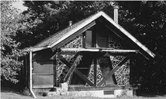
image4Подпись: Fig. 1.1: In 1975, the author, with his wife, jaki, built Log End Cottage, West Chazy, New York, using simple timber framing strategies "for the rest of us." Panels between posts are infilled with cordwood masonry.A nominal “two-by-four” today is actually 1V2 inches by 3У2 inches. All two-bys bought at large lumber suppliers such as Lowes and Home Depot are 1У2 inches thick. The actual depth of a two-by-four is fh inches (8.9 centimeters), and the depth of a two-by-six is 5У2 inches (14.0 centimeters). After that, the true depth is three-quarters inch (2 centimeters) less than the nominal dimension, so that a two-by-eight is jVa inches (18.4 centimeters) deep and a two-by-ten is 9lA inches (23.5 centimeters) deep. Sometimes, you can buy “heavy timbers” at large building suppliers, such as six-by-sixes, but these, too, lose one-half inch in the planer and have a true dimension of inches square. It is important to know the difference between “rough-cut” (full dimensional) timber and “finished” lumber, more commonly available.

This book does not discuss todays common stick-frame construction, because there are already a number of excellent manuals on the subject that I cannot improve upon. Some of these are listed in the Bibliography, but the list only scratches the surface of what is available. Also, there are building schools that teach this type of construction and they are noted in Appendix C. Many local trade schools and technical colleges also offer courses in conventional building.

Rather, Timber Framing for the Rest of Us is meant to complement natural building methods, in which the fabric of the building — cob, cordwood, straw bale, waddle-and-daub, etc. — is essentially infilling between the heavy timbers forming the buildings structural framework. Also, the methods described herein would be appropriate to storage sheds and barns where rough-cut lumber is to be used as siding. Unlike conventional stick framing, which is based upon the use of four – by eight-foot sheet goods, the center-to-center spacing of posts is typically

somewhere between six and ten feet (1.8 and 3 meters). This makes infilling much less tedious. Imagine trying to fill the narrow spaces in regular stud construction with cordwood masonry or straw bales.

People building heavy timber-frame structures do not normally buy much lumber at the large national lumber chain stores. Far more commonly, they will purchase their timbers from a local sawmill, make their own timbers with a chainsaw mill, or have a local sawyer visit their wooded property with a portable band saw, to have the standing trees converted to full-dimensional timbers. We’ll look at these options in Chapter 3.

If lumber dimensions were the only consideration, it could be fairly argued that a full-sized 2-by-8-inch floor joist or roof rafter (16 square inches or 103.2 square centimeters) would be 47.12 percent stronger on shear strength than its store-bought equivalent that measures 1.5 inches by 7.25 inches, or 10.875 square inches (70.16 square centimeters). That sounds pretty good, and is true as far as it goes, but there are other considerations that contribute to a timber’s strength.

Ferro-concrete pipes

Ferro-concrete pipes
Many perfectly know that such ferro-concrete pipes and where they are used. Truly, ferro-concrete pipes are very necessary in construction. Them use for transportation of household liquids, industrial, ground and atmospheric waters. Essentially, that waters did not destroy an internal surface of reinforced concrete. Very quite often pipes are used Continue reading

Provide a fence for safety and security

Installing a fence around your site is a good idea. It can deter or prevent the theft of tools and building materials. It also makes the site safer by discouraging unauthorized visits.

Подпись: NEATNESS COUNTS. A clean, well- organized job site enhances safety and improves construction efficiency. [Photo Roger Turk.J
Provide a fence for safety and security

Liability insurance is also a good idea, and it may even be required if you’re borrowing money from a bank. Always work to keep your site safe, organized, and free of debris, espe­cially boards with nails protruding from them. Stack unused materials neatly, keep trenches covered, and limit access to anv unsafe areas. One nail in a worker’s foot or a bad ankle sprain from tripping into a trench can cost a lot of time in medical attention and recovery.

Подпись: HABITAT HOUSES ARE AFFORDABLE AND EASY TO BUILD. Like most Habitat houses, this one (in Charlotte, N.C.) is designed to make economical use of basic building materials. STEP 3 Design the House

The bumper-sticker slogan, “Live Simply That Others May Simply Live,” speaks to the design aspects of an affordable house. To increase the cost of a house, all you need to do is compli­cate its design. Affordable housing is, by nature, small and simple. The same formula that makes for a safe house in earthquake country—small, low, and light—makes for an affordable house anywhere in the country.

Money-saving design ideas

The Charlotte house featured throughout this hook is one of the most cost-efficient designs you can build (see the photo at right). This single-story structure has a simple gable roof that extends over a small porch, where the main entry is located.

On a small lot, where setbacks seriously limit the footprint of the house, you may need to consider a small, two-story design. Habitat for Humanity has a good selection of basic house plans that fit the needs of most families (see Resources on p. 278). Admittedly, the bedrooms are not discotheque size, but you can do your dancing in the living and dining room. In a house, quantity of space doesn’t necessarily translate into quality of life. When my children were young, I enclosed our front porch and made two 5- ft. by 9-ft. rooms. They were cozy, sun-filled spaces; one was used for study, one for music. To my surprise, those two tiny rooms became the most popular parts of the house. A well-sited, well-designed house elicits that kind of reaction (see the sidebar on p. 10).

Another way to conserve space and save

money is to choose a floor plan that reduces

or eliminates hallways. As you look over a

house design, remember that doorways need

to be at least 32 in. wide—36 in. for easv

/

wheelchair accessibility. And keep in mind

that the direction in which a door swings can affect how well a room works and where you can place the furniture.

Other cost-saving strategies have more to do with materials and energy use. Keep the kitchen and the bath on the same side of the house to minimize rough plumbing expenses. In cold regions of the country, run plumbing lines in interior walls and enclose the porch as a mud room to minimize heat loss when com­ing and going. To find out which house designs work well in your area, seek advice from local builders, building inspectors, designers, or architects. You’ll find it’s not too difficult to modify basic plans to suit your needs and meet building-code requirements in your region (see Resources on p. 278).

Check with your building department to see whether your house is required to have a garage. Habitat for Humanity’s policy is to “build for people, not cars,” but some munici­palities require garages. Sometimes, however, you can get a variance sc vou don’t have to

4 <P 4

Подпись: Helping HandПодпись: Camp out! A great way to get information and inspiration for a new home design is to camp out on your building site. You'll learn about the path of the sun, prevailing breezes, and nice views.build a garage.

Helping Hand

Improve your design skills. Check with your local community college if you’re interested in learning how to read house plans or design a house. Most community colleges offer courses in computer-aided design, drafting, and con­struction management.

AND AIR-CONDITIONING

Heating and cooling systems are varied and com­plex, so make your house purchase contingent on a professional inspection by an HVAC contractor. In your walk-through, look for the following:

► If the bottom of the heating unit is rusted out or if it’s 15 years to 20 years old, it probably should be replaced. It’s certainly not efficient and probably not safe.

► Soot around heat registers or exhaust smells in living areas mean that the furnace is dirty and poorly maintained or that the furnace heat exchanger is cracked, allowing exhaust gases to escape. If an HVAC specialist can see flame through the heat exchanger, it’s definitely time to replace the unit. It may be a fire safety and health hazard.

► If your house has forced hot-air heat, your family could develop respiratory problems if the furnace has one of the older, reservoir-type humidifiers, which are notorious for breeding harmful organisms in the always-wet drum. An HVAC specialist can suggest alternatives.

► If certain rooms are always cold, an HVAC specialist may be able to balance heat distribution or add registers. That failing, you’ll need to upsize the furnace or boiler.

► If ducts, pipes, or the central heating unit are wrapped with white or gray paper-tape, your older heating system may be insulated with asbestos. Do not disturb it—an HVAC specialist can assess its condition and recommend an asbestos-abatement expert.

► Air-conditioning (AC) systems that run constantly but don’t cool may need the coolant to be recharged. An AC system that cycles too rapidly and makes the house too cold may simply be too large for the house. Both problems just need adjustments by an HVAC contractor.

FIREPLACE OR WOODSTOVE

Loose bricks in the fireplace firebox or smoke stains between the wall and the fireplace mantel (or surround) could allow flames or superheated

image57

AND EARTHQUAKES

In earthquake country, brick chimneys may break off at the roofline, fall through the roof, and harm inhabitants. A structural engineer can analyze the chimney and suggest remedies, such as seismic steel bracing of the chimney to the roof or removing the chimney above the roof and replacing it with metal flue pipe.

gases to ignite wood framing around the fire­place. A mason or chimney specialist can usually make necessary repairs.

If there are gaps between the hearth (firebox floor) and the hearth extension, stray coals could fall into the gaps and start a fire, so repoint gaps with mortar (if there’s brick) or grout (tile floors).

Local building codes usually specify mini­mum distances woodstoves and stovepipes must be from flammable surfaces. Ask to see a certifi­cate of occupancy (C. O.) issued for the existing installation. If the owner can’t produce one, make the C. O. part of your purchase agreement.

Estimating Project Difficulty and Costs

It’s hard to generalize how difficult a job will be for individual do-it-yourselfers because skills vary greatly. Still, it’s possible to suggest relative difficulties of various tasks, giving you some ref­erence at least. Chapters or sections of this book greatly expand on the following topics.

BEGINNER TO INTERMEDIATE

Demolishing. Make sure your tetanus shot is up to date. Before you begin work, wear full safety gear, including hard hat, eye protection, and boots that nails can’t puncture. If you will gener­ate dust, wear a dust mask. Also, prevent dust from migrating to other rooms by shutting or sealing door openings and air ducts with plastic. Always shut off power to an area you’re demol­ishing. During demolition, make sure you’re not compromising either the electrical system or the support structures. Be methodical, removing debris as you generate it, and sweep up the work site at the end of each day.

Interior painting. Preparing the walls and being fastidious are keys to success.

image58Подпись:Exterior painting. Rent scaffolding if it’s a two – story house. Homeowners often run planks between ladder brackets on extension ladders,

but the job will be far safer and many times faster if you work from scaffolding. Again, sur­face preparation is crucial to a lasting job.

Stripping paint, inside or out. This isn’t as dif­ficult as it is messy. Before you begin, buy a lead – paint testing kit from a building supplier. Lead paint dust and shavings are hazardous wastes and should be dealt with accordingly. Avoid open-flame paint stripping; the fire hazard is too great. Use a respirator mask with replaceable cartridges

Wallpapering. Practice on a small, out-of-the way area to get the hang of it. Wall prep is cru­cial. Use only the paste recommended by the wallcovering manufacturer.

Hanging drywall. This isn’t difficult if you’ve got help. Measuring carefully and getting the edges of the first sheets plumb (or level) are keys to success.

Patch repairing walls. This is generally quite easy. Sand or cut back the damaged parts to ensure a solid surface for the patch.

Insulating. Stuff or spray insulation into every nook and cranny to stop air infiltration. However, there should be air space over insulation between rafters, so that heated air under the roof can escape. Gloves, a long-sleeved shirt, a hat, and a face mask are imperative.

Weatherstripping. It’s easy but exacting work to fit the stripping snugly against doors, windows, and frames. You may be surprised how long this job takes.

GAP GRADATION

Our aim in designing an SMA’s aggregate structure has already been identified—a strong skeleton of coarse grains. Let us now consider what requirements an aggre­gate mix has to meet to create such a desirable skeleton. There is no room in it for too many fine or weak grains. The key solution for that question is gap gradation—that is, the right proportion of grains of defined sizes.

Let us start by examining a continuous gradation. If we want to design an aggregate mix with a maximum density (or otherwise, with a minimum void con­tent), we should create it from an aggregate with a roughly equal share of grains from consecutive fractions. In other words, such a mix should contain a propor­tionally even quantity of all fractions. We would call this type of gradation a continuous gradation. The appearance of grains of different sizes makes closer packing in a volume unit possible. This also minimizes the volume of voids among grains. Asphalt concrete is an obvious example of a continuously graded mixture (Figure 2.5; solid line).

So what is a gap gradation? Gap gradation is a disruption in the occurrence of consecutive aggregate fractions in an aggregate blend; that disruption results from a lack or minimal amount of one or more aggregate fractions. Looking at Figure 2.4, we can see the formation process of a skeleton with coarse grains and some of the finest grains but without the sizes in between. Gap gradation means a lack or minimal share of specified fractions of intermediate aggregates. The role of the gap gradation is so essential that the lack of definite size grains must be evident. But which fraction or sizes of grains or fractions? Here we have a couple of definitions and methods.

Federal Requirements Concerning Hazardous and Nonhazardous Waste

Projects that include purchase of new right-of-way, excavation, or demolition or modifica­tion of existing structures should be evaluated to determine whether there is any known or potential hazardous waste within the proposed project limits. Where hazardous substances are involved, adequate protection must be provided to employees, workers, and the com­munity prior to, during, and after construction. Typical materials that may constitute haz­ardous waste include pesticides, organic compounds, heavy metals, industrial waste, or other compounds injurious to human health and the environment.

Assessment of the potential presence of hazardous materials is conducted in two stages referred to as phases I and II. Phase I investigations are based on documentary research and visual observation to identify concerns and evaluate the likelihood that hazardous sub­stances have affected the property. Phase II includes the on-site collection of soil or water samples and completion of laboratory analysis to confirm that contamination is present. Phase I generally consists of historical research to evaluate current and past land uses and operations with a focus on what hazardous substances may have been introduced into the soil or water (including groundwater at the site); a search of regulatory records to evaluate whether the site or adjacent properties are listed in files as having violations, recorded haz­ardous substances releases or incidents, or a history of storing, handling, using, transport­ing, or disposing of hazardous substances; physical description of the soil geology and of surface water and groundwater, in order to evaluate the potential for migration of contam­inants from the source to another property; and a site walk to observe the site conditions and operations as well as those of the neighboring properties. Phase II is a specifically designed sampling and analysis program that effectively addresses the concerns raised in the Phase I study. Phase II should be designed to collect sufficient data to establish that a valid concern exists and to indicate what level of remediation may be required to address the concern. The American Society for Testing and Materials (ASTM) has developed a standard for completion of Phase I and Phase II investigations.

Resource Conservation and Recovery Act (RCRA). The Resource Conservation and Recovery Act was enacted in 1974, and amended in 1984, to address growing concerns related to disposal of hazardous and nonhazardous waste. RCRA requires states to develop EPA-approved hazardous waste management plans and encourages options other than landfill disposal for final disposition of hazardous waste. A major objective of RCRA is to conserve and protect environmental resources, including the land resource that is lost to other uses when it is filled with solid waste. RCRA established

• A system for defining hazardous waste

• A method to determine whether hazardous waste has been generated

• Guidelines on how to store, handle, or treat hazardous waste

• Standards for proper disposal of waste

• Methods to track hazardous waste to its ultimate disposition

Resource recovery is an important area mandated by RCRA, and covers several mate­rials used in highway construction, such as recycled glass, scrap tires, and recycled con­struction materials. Some hazardous materials can also be treated and recycled for use in highway construction. RCRA also covers issues of “use constituting disposal” for projects that seek to use embankments or road subbase as disposal areas for hazardous waste, if suit­ability can be demonstrated. Some of the research and demonstration projects in the area of resource recovery that are applicable to highways are discussed later in this chapter.

Toxic Substances Control Act (TSCA). The Toxic Substances Control Act sets the policy for testing suspected toxic substances to evaluate persistence in the environment and their effect on humans (acute toxicity levels and/or carcinogenic effects). TSCA also reg­ulates toxic substances not regulated by RCRA such as asbestos-containing materials (ACM) and polychlorinated biphenyls (PCBs), both of which may be found in existing highway facilities.

Comprehensive Environmental Response, Compensation, and Liability Act (CERCLA).

The Comprehensive Environmental Response, Compensation, and Liability Act was passed in 1980. It established national policy and procedures for identifying and remediat­ing sites that are found to be contaminated with hazardous substances, and identified pro­cedures for containing and removing releases of hazardous substances. CERCLA was amended and expanded by the Superfund Amendments and Reauthorization Act of 1986 (SARA). CERCLA established a hazard ranking system sites. The highest ranked sites have been placed on the National Priorities List (NPL) and are eligible for funding for envi­ronmental cleanup under CERCLA.

CERCLA provides for “joint and several liability,” which means that any party identi­fied as responsible for contamination of a site is considered equally responsible for cleanup costs with all other parties identified, and can be held 100 percent financially responsible in the event that other parties do not pay. Recovering costs from nonpaying parties is then the burden of the paying party and is pursued through the judicial system. Potentially responsible parties (PRPs) may be current or past owners and/or operators of a site where hazardous substances have been released, or persons who arranged for disposal or treat­ment of hazardous substances at the site. In addition, any person who knowingly accepted hazardous substances for transport to the site may be considered a PRP. Liability under CERCLA may also be retroactive to an era when the practices leading to the contamination were accepted industry standards. Petroleum is excluded from CERCLA unless mixed with other hazardous substances, in which case the entire mixture is considered hazardous. Provisions have been established under SARA for an Underground Storage Tank Trust Fund that will address petroleum releases.

A key concept mandated by CERCLA is “cradle-to-grave” responsibility for hazardous substances. Liability for a hazardous substance begins when it is accepted on the site or for­mulated at the site and continues after it is disposed off-site at a legally permitted facility.

CERCLA is important to the highway planning process primarily in the acquisition of right-of-way. Accepting financial liability for contaminated property may affect the finan­cial feasibility of a project. In addition, if significant cleanup must take place before high­way construction can begin, substantial delays to the project may result. The presence of contaminated materials along the alignment of a proposed highway alignment may be a crucial element in determining whether it is viable route. Careful evaluation of the nature and extent of the contamination as well as the cleanup alternatives, costs, schedule, and ongoing liability is warranted on all sites within a planned right-of-way purchase. Title III of SARA established mandatory federal standards for community right-to-know programs, and for reporting toxic chemical release by manufacturers.

Framing Lumber

Lumber is sized in “nominal," as opposed to number. For example, a piece of lumber that actually

Actual dimensions 1 3W" 1

Nominal 2 x 4 dimensions

Actual %"

1 3W" 1

Nominal 1 x 4

Framing Lumber Framing Lumber

“actual," dimensions. A nominal dimension rounds measures 1%”x 3%" is rounded off to the nominal off the actual dimension to the next highest whole 2” x 4”.

GWB = Gypsum wallboard (also called drywall or sheetrock). The most common thicknesses are V21 and 5/8".

Подпись: 3xo№eПодпись:

Подпись: Framing Sheathin Подпись: Although not as common in house framing, gypsum wallboard can be used on exterior walls, such as for apartments and condos, and commercial buildings for fire protection.
Подпись: У" — GWB 5/8" — GWB
Framing Lumber
Подпись: T&G Wood Structural Panels (tongue and groove)

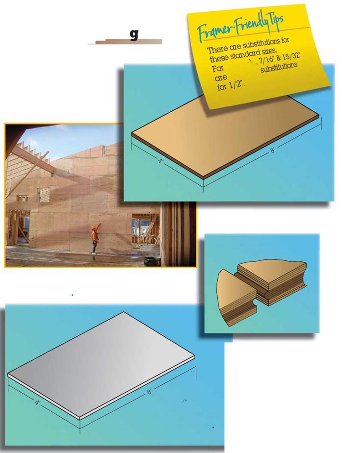
Framing LumberThe engineered panel products on this wall provide the strength needed for the high ceiling of this elementary school

Dens Glass® gypsum sheathing is a brand that has fiberglass mat, which provides mold and moisture resistance and is gold in color.

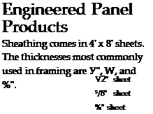
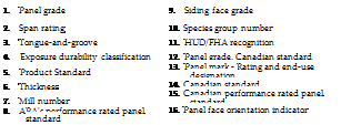
Engineered wood products can be divided into two categories: engineered panel products and engineered lumber products. Engineered panel products include plywood, oriented strand board (OSB), waferboard, composite, and structural particleboard. Engineered lumber products include I-joists, glu-lam beams, LVLs (laminated veneer lumber), PSLs (parallel strand lumber), and LSLs (laminated strand lumber).

Подпись: Engineered wood products are becoming more and more a part of our everyday framing. The strengths of these different products vary. Whenever you use engineered wood, it is important that you understand the qualities of the specific product you are planning to use, as well as structural considerations and any restrictions on cutting and installation.Engineered wood products have structural qualities different than those of traditional wood, so they must be used within the specification set by the manufacturer. When these products are specified on the plans, the architect or engineer who specified them will have checked with the structural engineer to ensure proper use.

Engineered panel products have been around for years and are treated in a

Подпись: Product

Подпись: I-joists are engineered panel products that provide consistency and fewer floor squeaks. Подпись: Plywood V2" sheet 5/8" sheet %" sheet

Framing LumberEngineered Panel

Framing LumberStagger (optional)

Leave space at all panel edge joints and У space at all panel end joints unless otherwise recommended by panel manufacturer.

2x joists, plywood-webbed I-joists or floor trusses.

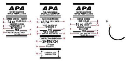
APA rated sheathing

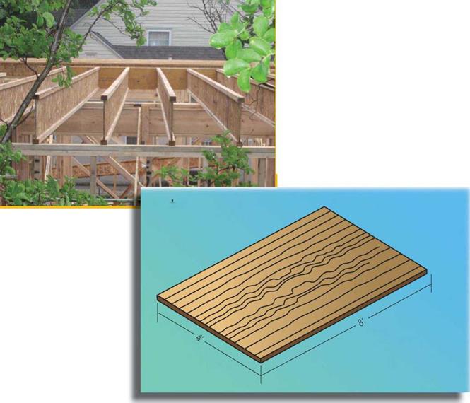
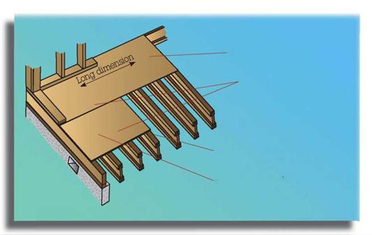
manner similar to engineered wood products. The 4′ x 8′ typical sheets are strongest in the direction of the grain. For floors and roofs, these sheets should be laid perpendicular to the direction of the supporting members. The strength of the panels comes from the panel cantilevering over the supports—so each piece should be at least as long as two support members.

Glu-lam beams, LVLs, PSLs, and LSLs can be cut to length, but should not be drilled or notched without checking with manufacturers’ specifications.

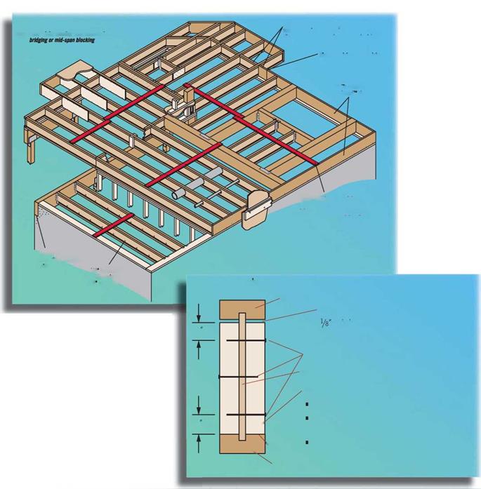
I-joists are becoming more widely used. Although the Engineered Wood Association has a standard for I-joists, not all I-joists manufacturers subscribe to that standard. Consequently, it is important to follow the manufacturer’s instructions whenever using I-joists. Installation instructions are usually delivered with the load for each job. The illustration shows some of the typical instructions.

Certain features are common among all I-joists. Rim and blocking may be of I-joist or solid rim board. Typical widths are 9%", 11 7/8 ", 14", 16", and 20".

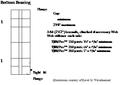
Web stiffeners are used to add to the strength at bearing points. If the bearing point is at the bottom flange, then the web stiffener, which is the thickness of the flange on one side of the web, is held tight to the bottom. There should be at least a 1/8" space between the top flange and the web stiffener. If the bearing point is at the top flange, then the web stiffener is held tight to the top with at least 1/8" between the bottom flange and the web stiffener.

Framing Lumber

B1 on-center (61 on-center for Til® 110

Framing Lumber

Silent Floor* joist framing does not require


Rim board joint between joists


Framing Lumber

Safety bracing (1×4 minimum) placed at


Framing Lumber
Framing Lumber
Framing Lumber

Common construction details for engineered lumber joists.


ІЛ. 0 0 ~W 0 0 . – Я-0 Tf, , -0 . S* ^ -0

section view of 1-joist. iJlease note tne components of the joist (darker colors) and the web stiffener (lighter color). Fasteners are shown in black.


Framing LumberFraming Lumber

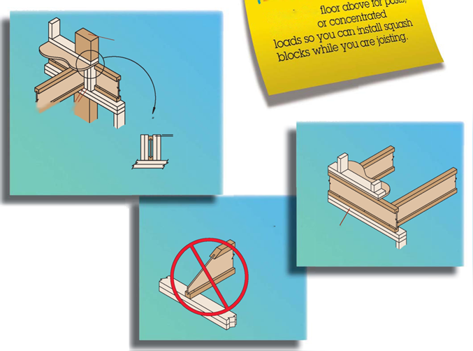
Framing LumberFraming LumberSquash blocks are pieces of lumber installed alongside TJI’s at points of heavy loading. They prevent the weight from crushing the TJI. They are typically dimensional lumber like 2 x 4s or 2 x 6s. They should be cut 1/іб" longer than the I-joist to take the load off the I-joists.

I-joists typically require a Ш" bearing. You can cut the end of an I-joist as long as it is not cut beyond a line straight up from the end of the bearing. However, no cuts should extend beyond a vertical line drawn from the end of the bearing point.

I-joist hardware, such as hangers, is usually delivered with the I-joist package. However, standard I-joist hardware can be purchased separately.

Check to-e

Подпись:Подпись: '/16coWirtoS,

V

2 x 4 minimum squash blocks (Illustrations courtesy of iLevel by Weyerhaeuser)

Подпись: DO NOT bevel-cut joist beyond inside face of wallПодпись: Rim board

Squash blocks should be 1/16" greater than the I – joist height.

Framing Lumber
Framing Lumber
Framing Lumber

Lumber


Framing

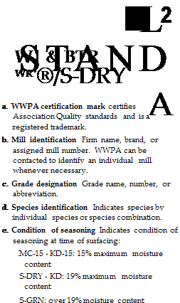
Grade

Use

Light framing

Construction

Plates

2 x 2 thru 4 x 4

Standard & better

Sills

Utility

Studs over 10′

Stud

Stud

Studs

2 x 2 thru 4 x 6 10′ or less

Cripples

Structural framing

Select structural

Joists

No.1

Rafters

No. 2

Headers

No. 3

Posts

Beams


Images of grade stamps courtesy of APA, The Engineered Wood Association and WWPA, the Western Wood Products Assocoiation


Framing LumberFraming Lumber

Framing Lumber

Framing Lumber

Chalk Line


Hammer


Marking

Crayon


Carpenter’s

Pencil


Framing Square


Tape


Try Square


Chisel


Hand Saw


Glue Gun


Speed

Square


Crowbar


Wall Puller


Sledgehammer


Tool Pouch

Framing Lumber


Flat Bar


Nail Puller or
Cat’s Paw


Framing LumberFraming LumberFraming Lumber

Framing Lumber

Framing Lumber

Reciprocating

Saw


Router


Electric Cord


Worm-drive Saw
(Circular Saw)


Drill


Chain Saw


Nail Gun


Air Hose


Air Compressor


Framing Lumber

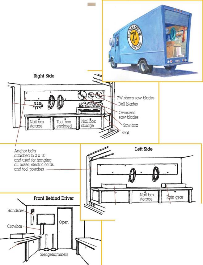
Подпись: Screw driver rack Подпись: Flat box for electric parts, Metal box air hose parts, drill bits, etc. for wrenches and sockets Подпись: SeatFraming Lumber

Pavements and Their Construction

Modern pavements normally comprise one or more bound layers overlying one or more unbound aggregate layers which, in turn, rest on the subgrade. In almost all cases the uppermost layers are bound by bitumen or cement. In the case of an embankment the subgrade is comprised of imported fill. In the case of a cutting it will often be the natural rock or soil at that location. Figure 1.5 provides two typical pavement profiles. Considering these from the bottom upwards, the following layers are, typically encountered:

• The pavement foundation consists of the natural ground (subgrade), and often a capping layer, the role of which is to improve the levelling, homogeneity and bearing capacity of the subgrade, and often also to ensure frost protection.

• The sub-base layer is normally comprised of an aggregate layer which acts as a platform for construction and compaction of the higher pavement layers and con­tinues to function during the life of the pavement as an intermediate distributor

Pavements and Their ConstructionПодпись:Pavements and Their ConstructionThin asphaltic ‘chip-seal’ (<30mm) Asphaltic or concrete Unbound aggregate layer(s) surfacing & base layers

= Base & Sub-base Unbound aggregate Sub-base

Soil improvement layer (Capping)

Natural or imported (fill) subgrade

of stress from the higher layers of the pavement down to the foundation. It may also have a frost protection role.

• The pavement base is usually comprised of treated materials in high-traffic pavements or may be untreated in low traffic pavements. These layers provide the pavement with the mechanical strength to withstand the loads due to traffic and distribute these loads to the weaker lower pavement layers.

• The surface course (and possibly a binder course below) is the top layer of the pavement, exposed to the effects of traffic and climate. It must resist traffic wear and also protect the structural layers, in particular against infiltration of water.

These are described more fully in Chapter 8. The higher volume cross-section is typical of those found in major highways. It is critical that it continues to function well, so drainage of these pavements is provided, principally, to maximise the life of the pavement structure and thus to minimise the cost. Although longevity is also an issue for the low volume pavement, it also needs drainage to perform at critical times – e. g. after heavy rain storms or during spring-thaw (see Section 1.8) – when it would otherwise become impassable.

The pavement construction is there to provide an almost fixed, plane surface on which tyred vehicles may pass without difficulty. To meet this requirement the surface:

• must not deflect much transiently – otherwise vehicles will be travelling in a depression of their own making and using excess fuel in a vain attempt to climb out of it;

• must not deform plastically – otherwise ruts will form, hindering steerage, lead­ing to increased fuel and tyre costs due to a greater contact with the tyre and tending to feed rainwater to the wheel path thereby promoting aquaplaning;

• must provide adequate skidding resistance – to enhance safety; and

• must continue to meet these requirements for a long time so that the pavement is economic and so that users are not unduly affected by pavement rehabilitation needs.

As far as the lower unbound layers and subgrades are concerned, they have to provide the necessary support to the upper layers so that those layers do not flex too much under trafficking as this could lead to those upper, bound, layers failing prematurely by fatigue. The upper layers need to be thick enough so that they spread the traffic loading so that the lower layers are not over-stressed and can provide their function successfully (Fig. 1.6). Successful pavement design is all about satisfying

Подпись: "A softened water subgrade ayyi cyaic subgrade Fig. 1.6 Malfunction of the lower pavement layers. A depression in an impermeable sub-grade allows water in the aggregate layer to collect there, leading to subgrade softening and consequent rutting of the whole pavement

these two needs in the most efficient manner given the properties of the available materials.

Federal Requirement Protecting Water Resources and Sensitive Ecological Resources

Clean Water Act (33 USC §1251 et seq. CWA). The CWA was enacted in 1977 as amend­ments to the Federal Water Pollution Control Act of 1972. Its stated goal is to “restore and maintain the chemical, physical, and biological integrity of the Nation’s waters.” The CWA gave EPA the authority to implement pollution control programs such as setting wastewater standards for industry. The CWA also contained requirements to set water quality standards

for all contaminants in surface waters, and provided funding for the construction of sewage treatment plants under the construction grants program. It also recognized the need for planning to address the critical problems posed by nonpoint source pollution.

One of the mechanisms to achieve the objectives of the CWA is the prohibition of dis­charges, including dredge and fill material, into navigable waters. The CWA made it unlawful for any person to discharge any pollutant from a point source into navigable waters, unless a permit was obtained under its provisions. Sections 402 and 404 of the CWA establish two complementary permit programs through which appropriate federal or state officials may authorize the discharge of pollutants.

Section 402 of the CWA has led to development of the National Pollutant Discharge Elimination System (NPDES) under which permits are issued for the discharge of material that is other than dredge or fill, including storm water runoff from highway facilities into navigable waters.

Under subsections 402(p)(2)(C) and (D) of the CWA, storm water permits are neces­sary for discharges from a municipal separate storm sewer system serving an incorporated or unincorporated area with a population over 100,000. The EPA definition of municipal separate storm sewer is “a conveyance or system of conveyances (including roads with drainage systems, municipal streets, catch basins, curbs, gutters, ditches, manmade chan­nels, or storm drains).” The definition goes on to specify that the system of conveyances may be owned by any of a number of types of municipal governing bodies and specifically includes states, that the conveyances must be specifically designed for the purpose of collecting or conveying storm water, and that they are not to be part of a combined sewer or part of a publicly owned treatment works (POTW).

Section 404 of the CWA has led to the development of a permit program adminis­tered by the USACOE for the deposition of dredged or fill materials into navigable waters. The definition of navigable waters has been contested in several recent Supreme Court decisions that have begun to limit the reach of the CWA permit authority in wet­lands to areas that have a significant nexus with navigable waters. In June 2007, the EPA and USACOE issued agency guidance regarding CWA jurisdiction following two of these recent decisions the consolidated cases Rapanos v. United States and Carabell v. United States [126 S. Ct. 2208 (2006)].

States often have overlapping jurisdiction with the USACOE regarding permitting of actions within navigable waters. State permits related to navigation and wetland encroach­ment are common and need to be taken into account when developing a project. State pro­grams are usually more restrictive, with a more expanded definition of wetland boundaries or a regulated buffer zone. In two states—Michigan and New Jersey—some permitting authority has been ceded to the state, simplifying the process.

The CWA prohibits storm waters from being used to transport or collect wastes and requires that standards for water pollution be established that do not diminish the uses of the water. EPA has the authority to develop a framework of regulation that can be fully del­egated to states once the EPA has approved their regulatory program. The CWA requires states to establish a policy of nondegradation that protects and preserves water (J. T. Dufour, California Environmental Compliance Handbook, California Chamber of Commerce, Sacramento, 1993, pp. 72-74).

In the preamble of the November 1990 amendments to the CWA, EPA explains its deci­sion to include state-owned highways as municipal separate storm sewers. EPA identifies dis­charges from state highways as a significant source of runoff and pollutants and as one of the “issues and concerns of greatest importance to the public” (Federal Register, Part II, Environmental Protection Agency 40 CFR 122, 123, and 124, November 16, 1990, p. 48039).

To avoid the problems associated with multiple permittees for systemwide discharges, the CWA regulations include a method whereby interconnected systems owned and oper­ated by local agencies and state-owned highways in areas of medium to high population may be combined into a single permit. The regulations allow the state transportation agency to be named as a copermittee in a systemwide permit, or to be named in a separate municipal permit. (E. M. Jennings, “Coverage of State Highways under Municipal Storm Water Permits,” Memorandum, Office of Chief Counsel, California State Water Resources Control Board, Sacramento, November 2, 1992, p. 31.)

Storm water systems owned by state highway departments in low-population areas (under 100,000) are not required to be permitted. Appendixes to Part 122 indicate the incor­porated areas and unincorporated counties in the United States with sufficient population to require municipal storm water permits. This information is shown in Table 1.10.

Application requirements for a group permit for discharges from large and medium municipal storm sewers fall into two parts. Also, an annual report must be submitted, as dis­cussed later.

Storm Water Permits for Construction. EPA in 1990 established final regulations for controlling storm water runoff from specific categories of industries and activities (40 CFR 122, 123, and 124). Any discharger of, or person who proposes to discharge, a waste other than to a sewer system, or changes the character of a current discharge, is required to report this activity to the local enforcement agency (Dufour, op. cit., p. 75). Once reported, the agency will evaluate the discharge and may

• Issue waste discharge requirements.

• Waive discharge requirements for insignificant discharges such as well testing or con­struction dewatering (no waiver is permitted if the discharge is to surface waters).

• Prohibit the discharge if sufficiently protective discharge requirements cannot be met by the discharger.

Discharge requirements are issued through an NPDES permit that specifies conditions the discharger must meet. The conditions are based on the established water quality objec­tives and the capacity of the existing storm water drainage system or receiving waters to assimilate the discharge. Discharge limitations are usually expressed as a combination of quantitative and procedural specifications. CWA provides for three types of NPDES per­mits: individual, group, and general. Issuance of waste discharge requirements must be noticed for public comment and approved at a hearing of the local authority (Ibid., p. 74).

The primary industrial category in the regulation relevant to building and maintaining highways is “construction activities.” Construction activities, in this context, include clearing, grading, and excavating that result in the disturbance of 5 acres or more of land that is not part of a larger (nonhighway) construction project. Construction sites were tar­geted because studies showed that the runoff from construction sites has high potential for serious water quality impacts. Sediment runoff from construction sites may be 10 to 20 times that from agricultural lands. Non-point-source pollutants from construction sites include sediment, metals, oil and grease, nitrates, phosphates, and pesticides.

To obtain an NPDES construction permit, a notice of intent must first be filed request­ing permit coverage at least 48 hours before construction begins. The NOI contains the following information:

1. Owner of the site (legal name and address) and contact person’s name, title, and tele­phone number. This entity must have control over construction plans and specifications, the ability to make changes, and day-to-day operational control.

2. Construction site information—whether the construction is part of a larger project or the portion of the site that is impervious both before and after construction activities. Site location must be provided as latitude and longitude. Indicate whether endangered or threatened species or designated critical habitats are present, as well as whether the project is on Indian Country Lands.

A. Incorporated places with populations of 250,000 or more

State

Incorporated place

Alabama

Arizona

California

Colorado District of Columbia

Birmingham Phoenix, Tucson

Long Beach, Los Angeles, Oakland, Sacramento, San Diego, San Francisco, San Jose Denver

Florida

Georgia

Illinois

Indiana

Kansas

Kentucky

Louisiana

Maryland

Massachusetts

Michigan

Minnesota

Missouri

Nebraska

New Jersey

New Mexico

New York

North Carolina Ohio

Oklahoma

Oregon

Pennsylvania

Tennessee

Texas

Virginia

Washington

Wisconsin

Jacksonville, Miami, Tampa

Atlanta

Chicago

Indianapolis

Wichita

Louisville

New Orleans

Baltimore

Boston

Detroit

Minneapolis, St. Paul

Kansas City, St. Louis

Omaha

Newark

Albuquerque

Buffalo, Bronx Borough, Brooklyn Borough, Manhattan Borough, Queens Borough, Staten Island Borough Charlotte

Cincinnati, Cleveland, Columbus, Toledo

Oklahoma City, Tulsa

Portland

Philadelphia, Pittsburgh Memphis, Nashville/Davidson

Austin, Dallas, El Paso, Fort Worth, Houston, San Antonio

Norfolk, Virginia Beach

Seattle

Milwaukee

B. Incorporated places with populations greater than 100,000 and less than 250,000

State

Incorporated place

Alabama

Alaska

Arizona

Huntsville, Mobile, Montgomery

Anchorage

Mesa, Tempe

(Continued)

TABLE 1.10 Population Areas That Require Storm Water Permits (Continued)

State

Incorporated place

Arkansas

California

Little Rock

Anaheim, Bakersville, Berkeley, Chula Vista, Concord, El Monte, Escondido, Fremont, Fresno, Fullerton, Garden Grove, Glendale, Hayward, Huntington Beach, Inglewood, Irvine, Modesto, Moreno Valley, Oceanside, Ontario, Orange

Colorado

Connecticut

Florida

Georgia

Idaho

Illinois

Indiana

Iowa

Kansas

Kentucky

Louisiana

Massachusetts

Michigan

Mississippi

Missouri

Nebraska

Nevada

New Jersey

New York

North Carolina

Ohio

Oregon

Pennsylvania

Rhode Island

South Carolina

Tennessee

Texas

Aurora, Colorado Springs, Lakewood, Pueblo

Bridgeport, Hartford, New Haven, Stamford, Waterbury

Fort Lauderdale, Hialeah, Hollywood, Orlando, St. Petersburg, Tallahassee

Columbus, Macon, Savannah

Boise City

Peoria, Rockford

Evansville, Fort Wayne, Gary, South Bend Cedar Rapids, Davenport, Des Moines Kansas City, Topeka Lexington-Fayette Baton Rouge, Shreveport Springfield, Worcester

Ann Arbor, Flint, Grand Rapids, Lansing, Livonia, Sterling Heights, Warren Jackson

Independence, Springfield Lincoln

Las Vegas, Reno

Elizabeth, Jersey City, Paterson

Albany, Rochester, Syracuse, Yonkers

Durham, Greensboro, Raleigh, Winston-Salem

Akron, Dayton, Youngstown

Eugene

Allentown, Erie

Providence

Columbia

Chattanooga, Knoxville

Abilene, Amarillo, Arlington, Beaumont, Corpus Christi, Garland, Irving, Laredo, Lubbock, Mesquite, Pasadena, Plano, Waco

Utah

Virginia

Salt Lake City

Alexandria, Chesapeake, Hampton, Newport News, Portsmouth, Richmond, Roanoke

Washington

Wisconsin

Spokane, Tacoma Madison

C. Counties with unincorporated urbanized areas with population of 250,000 or more

State

County

California

Delaware

Florida

Georgia

Hawaii

Maryland

Texas

Utah

Virginia

Washington

Los Angeles, Sacramento, San Diego

New Castle

Dade

De Kalb

Honolulu

Anne Arundel, Baltimore, Montgomery, Prince Georges

Harris

Salt Lake

Fairfax

King

D. Counties with unincorporated urbanized areas with population greater than 100,000 and less than 250,000

State

County

Alabama

Jefferson

Arizona

Pima

California

Alameda, Contra Costa, Kern, Orange, Riverside, San Bernardino

Colorado

Arapahoe

Florida

Broward, Escambia, Hillsborough, Lee, Manatee, Orange, Palm Beach, Pasco, Pinellas, Polk, Sarasota, Seminole

Georgia

Clayton, Cobb, Fulton, Gwinnett, Richmond

Kentucky

Jefferson

Louisiana

East Baton Rouge Parish, Jefferson Parish

Maryland

Howard

Nevada

Clark

North Carolina

Cumberland

Oregon

Multnomah, Washington

South Carolina

Greenville, Richland

Virginia

Arlington, Chesterfield, Henrico, Prince William

Washington

Pierce, Snohomish

Source: Adapted from Federal Register, vol. 55, no. 222, November 16, 1990, pp. 48073, 48074.

3. Scheduled beginning and ending dates of construction.

4. Identification of the receiving body of water, and storm water drainage information including a site map.

5. Type of construction activity: transportation should be indicated if the project is a road­way; utilities should be indicated for the installations of sewer, electric, and telephone systems.

6. Material handling and management practices indicating the type of material to be stored and handled on site and the management practices to be used to control storm water pollution.

7. Regulatory status of the site, including approval status of the erosion or sediment control plan.

8. Signature of the owner of the site certifying that the information is accurate.

Most statewide NPDES permits for general construction activities require the permit holder to develop and implement a storm water pollution prevention plan (SWPPP) using either best available technology economically achievable (BAT), best conventional tech­nology (BCT), or best management practices (BMPs) to control pollutant discharge both during and after construction activities. Once prepared, the SWPPP will be maintained at the construction site by the highway department representative and made available on request by the local enforcement agency. All contractors and subcontractors working at the site are responsible for implementing the SWPPP. The SWPPP will generally include the following components:

1. Location, including a 1/4-mi vicinity map that shows nearby surface water bodies, drainage systems, wells, general topography, and location where storm water from the construction activities will be discharged, including MS4s.

2. A site map that indicates the total site area and total area to be disturbed. This map should indicate the location of the control practices to be implemented, areas where wastes and soils will be stored, drainage patterns for the site both before and after con­struction activity, areas of soil disturbance, areas of surface water, potential soil ero­sion areas, existing and planned paved areas, vehicle storage areas, areas of existing vegetation, and areas of postconstruction controls.

3. A narrative description of the construction site, project, and activities. This should include a description of the fill material and native soils at the construction site and the percentage of site surface area that is impervious both before and after construction activities.

4. A narrative description of toxic material used, treated, or disposed of at the construction site.

5. Identification of potential sources of storm water pollution, and name of receiving water.

6. Proposed controls and best management practices during construction, including description of

• State and local erosion sediment control requirements

• Source control practices intended to minimize contact between the construction equipment and materials and the storm water being discharged

• Erosion and sediment control procedures to be implemented

• Plan to eliminate or reduce discharge of other materials into the storm water

7. Proposed postconstruction waste management and disposal activities and planned controls, including a description of state and local erosion and sediment postclosure control requirements.

8. Estimated runoff coefficient for the site, estimated increase in impervious area follow­ing the construction, nature of fill, soil data, and quality of discharge.

9. List of the contractors and their subcontractors who will be working at the construction site.

10. Employee training.

11. Maintenance, inspection, and repair activities.

Control measures for sediment include grading restrictions, runoff diversion, application of straw bales and filter fabric, revegetation requirements, and retention basins. Control measures for other pollutants include roof drains, infiltration trenches, grassy swales to detain storm water to allow sediments to settle out, oil/grit separa­tors, detention basins, and proper management practices such as the proper applica­tion of fertilizers and pesticides.

Another approach used to implement the NPDES program for state highway agencies is to issue comprehensive permits for all relevant highway construction, maintenance, and operations activities in areas meeting the population requirements outlined in 40 CFR 122.26. The benefit of a comprehensive permit is the management efficiency of adminis­tering the permit from both the regulatory agency and highway department perspectives.

In California, for instance, the California Regional Water Quality Control Board (RWQCB) is responsible for issuing storm water discharge permits. The RWQCB in the San Francisco Bay area has issued a comprehensive NPDES permit for storm water dis­charged directly or through municipal storm drain systems to lakes, water supply reser­voirs, groundwaters, the Pacific Ocean, San Francisco Bay, San Pablo Bay, Suisun Bay, the Sacramento River Delta, or tributary streams or watercourses and contiguous water bodies in the San Francisco Bay region (District 4 and portions of District 10 of the California Department of Transportation, or Caltrans).

Provisions of the permit cover maintenance operations and include requirements to submit plans for maintenance activities that affect storm water discharges and to improve practices that will result in reduction of pollutants in discharges. Road sweeping plans, storm drains, catch basins, inlet and channel maintenance, and vegetation control plans are required. Caltrans must prepare storm water pollution prevention plans for maintenance facilities that cover such activities as vehicle and equipment maintenance, cleaning, fuel­ing practices, and storage and handling of construction materials, fertilizers, pesticides, paints, solvents, and other chemicals.

Under the provisions of the permit, Caltrans must rank construction activities on the basis of their potential impacts on receiving waters from pollutants in storm water dis­charges. Plans must be developed for erosion control, chemical and waste management, and postconstruction permanent features. Training is a key component of these plans.

The permit also encompasses permanent control measures for the management of storm water draining from Caltrans rights-of-way in areas meeting the population criteria. Consideration must be given to high-risk areas where spills may occur and must include a plan to reduce the pollutants discharged into the system over time. This portion of the permit requires Caltrans to develop mechanisms to control illegal dumping, to respond to accidental discharges, and to identify and control procedures for discharge in a category not expressly prohibited by the permit.

The RWQCB included specific provisions to assist in meeting water quality goals. For example, requirements of the permit include specific measures to reduce the mass load of copper in storm water discharges.

Monitoring plans and annual reports are also required in the NPDES permit and are gen­erally consistent with these provisions in standard construction and/or municipal storm water permits.

Sustainable storm water management practices have been evolving over the last 20 years, but it has been only during the last decade that the movement has gained momentum and designers are looking toward best management practice and low impact design solutions to storm water issues. These design concepts use the natural capacity of the environment to detain, filter, and reduce (through evaporation and transpiration) the runoff from a roadway facility. Relying on these natural systems, rather than engineered water conveyance and discharge infrastructure, can

• Reduce regulatory burden and time in gaining approval for the project.

• Improve the function of treatment plant—reduce combine sewer outfills.

• Improve the environment—using design measures to create wetlands and other habitat.

• Gain community buy-in.

• Reduce costs.

Wetlands Involvement (Executive Order 11990). Under Executive Order 11990, the fol­lowing procedures must be followed for any federal action that involves wetlands:

• An opportunity for early public involvement must be provided for actions involving wetlands. For those actions requiring either a FONSI or an EIS, any notices for a public hearing, or an opportunity for a hearing, must indicate if any alternatives are located in wetlands. At any hearing, the location of wetlands must be identified. A newspaper notice inviting written comments must be published prior to issuance of a categorical exclusion.

• Alternatives that would avoid wetlands must be considered, and if avoidance is not possible, measures to minimize harm to wetlands must be included in the action. Documentation of these avoidance requirements must be included in an EA or EIS.

• A wetlands-only-practicable-alternative finding must be prepared for actions requiring a FONSI or an EIS (FHWA Technical Advisory T6640.8A).

Floodplain Involvement (Executive Order 11988). Executive Order 11988 require addi­tional steps in the environmental review process for actions that encroach on floodplains. Specifically, the public must be given the opportunity for early review and comment, and notices must reference potential encroachments on the base floodplain. In addition, floodplain-only-practicable-alternative finding must be prepared for actions involving a significant encroachment (see FHWA Technical Advisory T6640.8A). This finding must be included in the final environmental document.

A floodplain evaluation must be prepared and summarized in the environmental docu­ment in accordance with federal regulation (23 CFR 650, Subpart A). This floodplain eval­uation should contain a project description, including a map of the project showing the base floodplain and all project encroachments, as well as alternatives to encroachment. A dis­cussion should be provided of the practicality of alternatives that would avoid longitudinal or significant encroachments.

The floodplain evaluation should be summarized in the EA or EIS. The portions of the evaluation pertaining to fish and wildlife, vegetation, wetlands, growth inducement, etc., are to be included in the respective sections of the EA or EIS. Summaries involving flood­plains in general, as well as hydraulics and risk, are to be included in a section entitled Floodplains.

Safe Drinking Water Act. The Safe Drinking Water Act (SDWA) was enacted in 1974 to protect the nation’s drinking water supply and protect public health through appropriate water treatment technologies. The SDWA applies to all of the more than 160,000 public water sys­tems in the United States. SDWA establishes maximum contaminant levels (MCLs), or stan­dards for the maximum safe levels of specific constituents in potable water. Important to highway engineers is the provision of SWDA that mandates protection of sources of drinking water. The SDWA requires the protection of drinking water and its sources: rivers, lakes, reservoirs, springs, and groundwater wells. The location of these resources, therefore, becomes an early consideration in the siteing and design phases of a project.

Federal Endangered Species Act. The Federal Endangered Species Act of 1973 (16 USC §§1531-1543) provides a means whereby the ecosystems upon which endangered species and threatened species depend may be conserved. It also provides a program for the con­servation of such endangered and threatened species. Section 7 of the act requires each fed­eral agency, in consultation with the Secretary of the Department of the Interior, to ensure that actions authorized, funded, or carried out by a federal agency do not jeopardize the continued existence of any endangered or threatened species or result in the destruction or adverse modification of habitat of such species unless such agency has been granted an exemption for such action.

For federal highway projects, a request is made to the U. S. Fish and Wildlife Service (FWS) regarding whether any species listed or proposed as endangered are present in the project area. If so, a biological assessment must be completed and reviewed by the FWS. The FWS will make a determination as to the impacts on critical habitat or on the species itself and whether the impacts can be mitigated or avoided. An exemption from the Endangered Species Act must be obtained where a project would result in impacts to endangered species.

The level of involvement with the endangered species process can vary widely from project to project, but will generally involve the following steps:

• Establish an area of potential environmental impact (APEI) and potential for conflict with endangered species.

• Once preliminary alternatives are selected, determine whether a request for a species list from the FWS is required and then request a list, through FHWA, if required.

• Perform and document a biological assessment.

• If there are no species present or there will be no effect, obtain FWS concurrence through FHWA before circulating the draft environmental document under NEPA.

• If the preferred alternative affects species, request conference or consultation with the FWS through FHWA, which must be completed before the final environmental docu­ment under NEPA can be approved.

Rivers and Harbors Act. The Rivers and Harbors Act of 1899 (33 USC 401 et seq. RHA) was enacted to protect navigation and the navigable capacity of the nation’s waters. Two provisions of the act have to potential to significantly affect highway projects proposed in or around U. S. harbors or rivers are

• Section 9 of the RHA, which requires a permit for the construction of bridges or cause­ways across navigable waters of the United States

• Section 10 of the RHA, which requires a permit for various types of work performed in navigable waters, including stream channelization, excavation, and filling

The permit jurisdiction is divided between two agencies. The Section 9 bridge permit is the responsibility of the USGS. Section 10 for construction activities performed in the water is within the jurisdiction of the USACOE. Although often issued together, this permit has independence from a permit issued under Section 404 of the Clean Water Act.
Concept of Reliability Engineering

The basic idea of reliability engineering is to determine the failure probability of an engineering system, from which the safety of the system can be assessed or a rational decision can be made on the design, operation, or forecasting of the system, as depicted in Fig. 1.3. For example, Fig. 1.4 schematically illus­trates using reliability analysis for risk-based least-cost design of engineering infrastructures.

An infrastructure is a functioning system formed from a combination of a number of components. From the perspective of reliability analysis, infras­tructure systems can be classified in several ways. First, they can be grouped according to the sequential layout of the components (Fig. 1.5). A series sys­tem is a system of components connected in sequence along a single path, i. e., in series. Failure of any one of the components leads to failure of the entire system. A parallel system is one with its components connected side by side,

i. e., in parallel paths. Many engineering systems have built-in redundancy such that they function as a parallel system. Failure occurs when none of the parallel alternative paths function. Second, from the view point of the time consistency of the statistical characteristics of the systems, they can be classified as a time – invariant statistically stationary system (or static system) and a time-varying statistically nonstationary system (or dynamic system).

Infrastructures may follow different paths to failure. The ideal and simplest type is the case that the resistance and loading of the system are statistically independent of time, or a stationary system. Most of the existing reliability analysis methods have been developed for such a case.

A more complicated but realistic case is that for which the statistical char­acteristics of the loading or resistance or both are changing with time, e. g., floods from a watershed under urbanization, rainfall under the effect of global

D


E

Q


D


00

2


D


Concept of Reliability Engineering

♦ D


Concept of Reliability EngineeringConcept of Reliability EngineeringConcept of Reliability EngineeringConcept of Reliability EngineeringConcept of Reliability Engineering

Concept of Reliability Engineering

Подпись: ОПодпись: DConcept of Reliability EngineeringFigure 1.4 Risk-based least-cost design of infrastructural sys­tems. (After Yen and Tung, 1993.)

warming, sewer or water supply pipes with deposition, and fatigue or elastic behavior of steel structure members. This case can further be subdivided into the subcases of (1) the changing process is irreversible and accumulative and (2) the changing process is reversible, e. g., repairable. For some infrastructures, the statistical characteristics of the system change with space or in time (or both), e. g., a reach of highway or levee along different terrains. There are other subsets ofthese time-varying or space-varying dynamic failure cases. One is the subcase that a component of the system already has malfunctioned, but failure has not occurred because the loading has not yet reached the level of such failure, or there is a redundant component to take the load, but the strength of the system is weakened. Another subcase is changing the tolerance of failure, such as changing acceptable standards by regulations.

Concept of Reliability Engineering

(a)


Figure 1.5 Typical configura­tions of infrastructural systems: (a) series system; (b) parallel system.


Concept of Reliability Engineering