Work Begins
 Former Earthwood student Doug Kerr visited for a week to help out on the early stages of the project. He wanted to learn timber framing, but didn’t want to wait for the book. Doug arrived in the evening, and the next morning we tore up the entire front sitting deck, and all of the original four-byeight deck joists. The post-and-beam frame of the original solar room’s south wall was still in excellent condition.


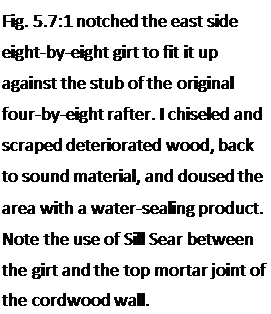
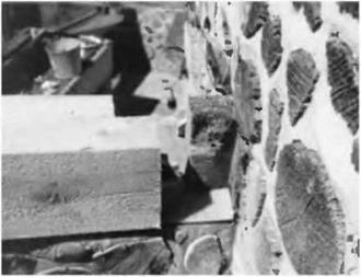
 The east and west walls of the lower story were 16-inch cordwood walls, and, for insulation and architectural purposes, we wanted to maintain that same width and style in the new addition. I chose to install new cedar eight-by-eight girts where the old deteriorated doubled four-by-eights had been removed. The south end of the eight-by-eight would be supported directly by the six-by-ten girder that ran along the south side of the original solar roof. But how would we fasten the northern ends of these girts? Improvisation. There was enough of a stub on each of the original four-by-eight floor joists to fasten to, as seen in Fig. 5.7. With my chainsaw, I removed a 4- by 4-inch by 8-inch-high (10.i – by 10.1-centimeter by 20.3-centimeter-high) chunk of wood from the new cedar girt, and fastened it to the stub using two seven – inch (180-millimeter) lag screws.
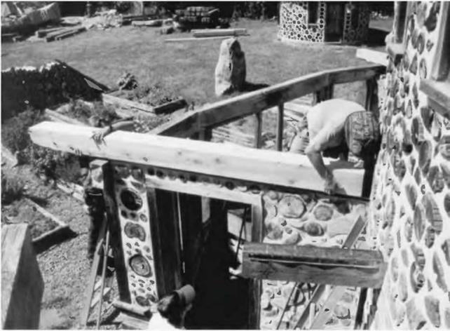
Remember that the cordwood wall would also be supporting this girt all along its length. Fig. 5.8 shows the east wall girt being installed.
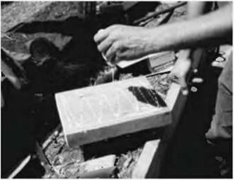
situations. The center floor joist had only 6V2 inches 16.5 centimeters) of good sound four-by-eight extending from the wall. As it was the center joist, maintaining symmetry was important. In this case, we used a wooden gusset system, the gussets made from two scrap pieces of two-by-eight material, each about a foot long. In Fig. 5.9, I apply wood glue to one side of one of the gussets. In many instances, gussets are made of plywood, such as with homemade trusses. I didn’t have plywood at the ready in this case, and, as the join would be exposed, I figured that the two-by-eight pieces would look better anyway. Gussets used in this fashion must be used in pairs, one each side of the joint, just like truss plates on trusses. Otherwise, most of the strength of the joint is lost.


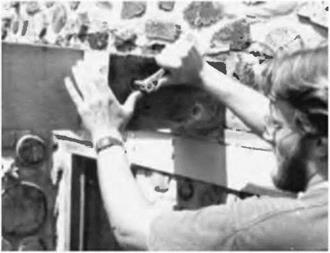 In Fig. 5.10, I used an electric drill to mount the glued gusset to the two four – by-eights which are butted together. I used four screws on each side of the joint. Half of the gusset (six inches or 15.2 centimeters) was screwed and glued to the original stub, and the other half was similarly fastened to the new joist. The gusset on the other side got the same treatment.
The remaining two joist extensions were a different situation, so we used a different solution. The original joists extended into the space about eighteen inches (45.7 centimeters), and symmetry was not an issue, the way it was in the center. So in this case, we simply fastened the new four-by-eight alongside of the original member, using glue and two strong one-half-inch by 8-inch (1.2- by 20.0-centimeter) carriage bolts. Carriage bolts have rounded heads and a square section just under the head that grabs the wood by pressure and friction. The trick
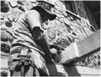
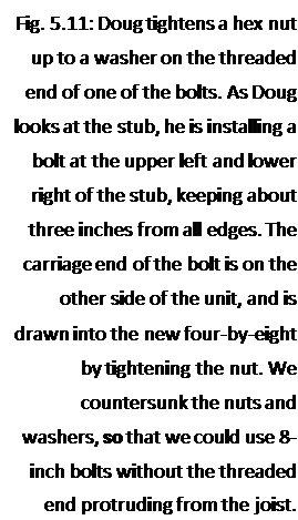
here is to join the rafters together temporarily while a half-inch hole is drilled all the way through both. There are a variety of clamps that will work for this purpose, or you can temporarily toe-screw the two pieces together while you drill. Again, glue between the pieces makes for a stronger joint. In our case, I used just two large bolts to make the joint. See Fig. 5.11.


 Fastening the Joist to the Girder
The nice thing about wide joists like four-by-eights and five-by-tens is that they are stable when supported by a wall or girder, unlike two-bys, which can fall over quite easily. Cross-bracing or bridging of two-bys is not only prudent, but building codes require it.
Another nice thing about heavy joists is that they are esthetically pleasing, particularly when the depth of the timber is twice as great as its breadth.
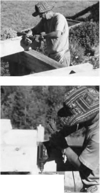
Four-by-eights are very stable over the girder, but they must still be fastened, so that they don’t slide laterally. In Fig. 5.12,1 am toe-screwing the joist to the six – by-ten girder. In Fig. 5.13, I use a right-angle galvanized plate to hold the joist in its correct position over the girder.


Leave a reply